Sukesh N. 1, Lakshmisagar P. S. 2, Girish Kumar 1
1Department of Mechanical Engineering, S. D. M. Institute of Technology, Ujire, India
2Department of Physics, S. D. M. Institute of Technology, Ujire, India
Correspondence to: Sukesh N. , Department of Mechanical Engineering, S. D. M. Institute of Technology, Ujire, India.
| Email: |  |
Copyright © 2015 Scientific & Academic Publishing. All Rights Reserved.
Abstract
Photovoltaic thermal (PVT) absorbers utilize solar energy for developing electric as well as thermal energies simultaneously. The conversion of thermal energy depends on efficient heat extraction process from the photovoltaic panel. Metallic absorbers with various designs of fins and flow arrangement are being used for the purpose. In this work, the effects of absorber material, heat transfer coefficient and geometrical parameters on the performance of finned absorber plate for small photovoltaic application have been investigated. Simulations and numerical calculation infer that copper is the ideal choice for absorber and fin material owing to its high thermal conductivity. The fin spacing and absorber thickness have significant effect on the amount of heat transferred and effectiveness of fins.
Keywords:
PVT absorber, Fins, Thermal conductivity, Heat transfer coefficient
Cite this paper: Sukesh N. , Lakshmisagar P. S. , Girish Kumar , Heat Transfer Analysis of Fin Performance for PVT Absorber, Journal of Mechanical Engineering and Automation, Vol. 5 No. 3B, 2015, pp. 1-4. doi: 10.5923/c.jmea.201502.01.
1. Introduction
PV system utilizes energy from sun to deliver electrical energy. III-V multi-junction solar cells (MJSCs) are found to display conversion current efficiency of 35-40% [1]. Rest of the 60% of energy is wasted as heat. Hence there is a need to cool the cells in order to keep them in the safe working range. In addition, the heat energy received by the stream of fluid can also be tapped as useful work. The very idea of such hybrid systems comes from the fact that more than 50% of incident solar radiation is wasted as heat which is detrimental to the PV cell efficiency. There is a great deal of research going on in the field to develop PVT technology for practical applications at reasonable cost [2-5]. The Figure 1 is a schematic representation of hybrid PVT system. The components are PV module, absorbing metal plate and cooling channels/tubes. The solar radiation falling on the PV cell results in the generation of electricity with a large fraction of the incident energy goes to absorber in the form of heat. The tubes/channels provided underneath carry a coolant fluid (air/water/any other liquid) draws heat from the absorber and keeps the unit cool. By doing so, it prevents the deterioration of conversion efficiency. 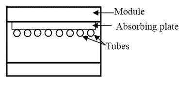 | Figure 1. Components of PVT system |
It is well known that the electrical efficiency of PV modules depends mainly on the incoming solar radiation and the PV module temperature. On the other hand, the thermal efficiency of the PVT module depends on the incoming solar radiation and the input fluid/ambient temperature. In hybrid systems, the temperature of the module depends not only on solar radiation and ambient conditions, but also on the system operating conditions. This, in turn, affected by the temperature of heat extraction fluid flowing through the thermal unit mounted on the PV module rear surface. It was observed that both electrical and thermal efficiencies were higher at higher ambient temperatures [6].Heat transfer analysis on virtual systems can be carried out easily in quick time with the advent of simulation tools. This approach also saves a large amount of experimental efforts. However, sufficient care should be taken while selecting the boundary conditions and setting the parameters, as improper selection may lead to faulty results [7]. In the present work, numerical simulation is used to assess the performance of absorber-fin system for small PVT module of 2 kW output.
2. Experimental
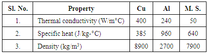
Temperature profile of absorber-fin system is studied using Mechanical ANSYS 12.0 Parametric Design Language software module. The absorber is presumed to have a heat transfer cross section of 50 X 50 mm2. The back panel of a solar cell when used with 35 sun concentration would be expected to attain a temperature of 150°C, which, in turn is used as input temperature for the absorber plate. The lateral surfaces of the absorber are treated as insulated and heat transfer through the geometry is assumed to be one dimensional. Fluid is made to flow over fins to extract heat from the absorber. The ambient temperature is taken as 30°C.While simulating the absorber-fin system, material properties are assigned and free meshing is carried out to the model using 2-D quadrilateral element (PLANE55). PLANE55 is a four node element with single degree of freedom (temperature) at each node and has thermal conduction capability [8]. Boundary conditions are incorporated and simulations are performed to study the effect of following parameters on the heat transfer performance of the fins for PVT absorber applications. ● The material used for making the absorber plate and fin: Three different materials, namely, Copper, Aluminium and Mild Steel (M. S.) are used for evaluation. The materials are chosen on the basis of thermo-physical properties, ease of fabrication and economic viability. The properties of the selected materials are presented in Table 1.Table 1. Thermo-physical Properties of Absorber Materials [9]
 |
| |
|
The 2-D schematic of PVT absorber-fin system is shown in Figure 2.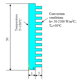 | Figure 2. Absorber geometry with boundary conditions (dimensions are in mm) |
● The heat transfer coefficient (convection conditions): The flow conditions and convection environment for heat transfer purpose are generally characterized using heat transfer coefficient (HTC). It is established that free and forced convections with water as the fluid would give rise to convection coefficients in the range 50 – 50,000 W/m2 °C [10]. In this work, simulations are carried out for heat transfer coefficients 50 – 2500 W/m2 °C.● The dimensions and spacing of absorber-fin assembly: The simulation trials have been carried out to estimate the appropriate combination of absorber thickness, length, thickness and spacing of fins to obtain optimum heat transfer performance. Initial simulations are carried out for 12 fins of 5 mm length with 2 mm spacing projected from the absorber of 5 mm thickness. To study the effect of fin length, the analyses are also carried out for the fin lengths 2.5 mm, 7.5 mm and 10 mm. To study the effect of spacing on heat transfer, the number of fins is varied keeping the area of exposure constant. The spacing and length of the fins are modified accordingly. The absorber thickness is reduced from 5 mm to 2 mm in steps of 1 mm in order to determine its effect on heat transfer.
3. Results and Discussion
The absorber-fin system thermal profiles are generated using simulations for three materials and twelve heat transfer coefficients. The Figure 3 shows the typical thermal profile of an absorber-fin system. There is a gradual drop in the temperature from the base to the tip in all the cases although the extent of drop varies from case to case. The temperatures at the base and tip of the fin are estimated from the simulations and graphically represented in Figure 4.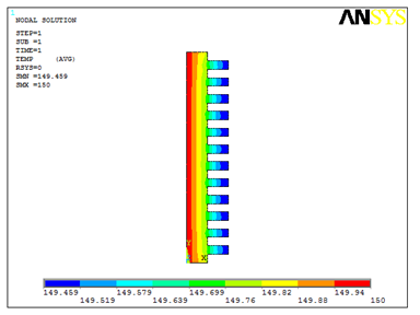 | Figure 3. Thermal profile for Copper absorber (h=50 W/m2°C, 12 fins, 2 mm spacing) |
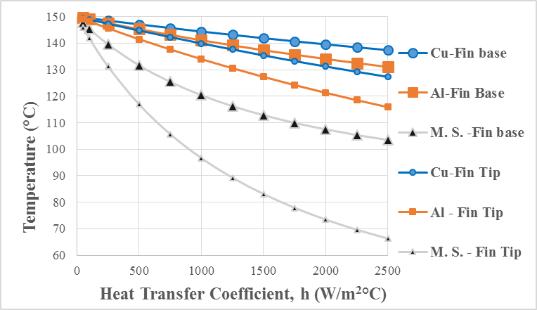 | Figure 4. Variation of temperature in fin with HTC |
It is inferred that copper is most effective in transferring the heat compared to Aluminium and Mild Steel. Smaller temperature gradient existing between absorber base-fin base and fin base-fin tip when copper is used as material is the indication of the same. For example, at heat transfer coefficient of 250 W/m2 °C for the input temperature of 150°C, Copper fin experienced temperature of 148.52°C at the base and 147.34°C at the tip. For the same input temperature and heat transfer coefficient, the base and tip temperatures for Aluminium and Mild Steel fins are lower (147.57°C and 145.62°C for Aluminium and 139.56°C and 131.21°C for Mild Steel). In other words, a temperature gradient of 1.18°C was present in Copper fin whereas the temperature gradients in Aluminium and Mild Steel were 1.95°C and 8.35°C respectively. This is attributed to lower thermal resistance offered by copper to heat flow compared to Aluminium and Mild Steel. At higher heat transfer coefficients this effect is more pronounced as seen from Figure 4. Large thermal gradients exist in M.S. compared to Cu or Al (Figure 5) indicates that M.S. stores more thermal energy rather than transferring it. Hence, the choice of M.S. for fin applications is not suggested from heat transfer consideration. On the other hand, the use of Cu for such applications highly recommended as already seen. Further, Aluminium, which has heat transfer performance closer to copper, can also be used as absorber material due to its lower density and cost.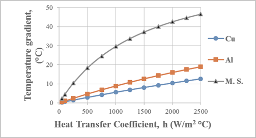 | Figure 5. Variation of Thermal gradient in absorber-fin assembly with HTC (12 fins, 5 mm length, 2 mm spacing) |
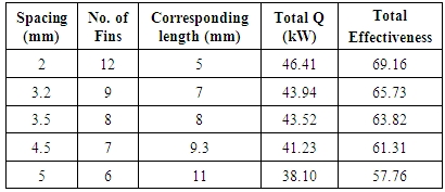
Further analyses are carried out for copper material at 2500 W/m2 °C only as this combination results in better heat transfer performance. For a given number of fins, varying the fin length causes significant variation in thermal gradients in the absorber (2.5°C, 12.62°C, 19.17°C and 20.61°C for the fin lengths of 5 mm, 7.5 mm and 10 mm respectively). Lower the gradient in the absorber more is the heat available for the fluid to extract and better will be the thermal efficiency. However, increasing the length beyond 10 mm has not resulted in notable difference in the gradients.Increasing fin spacing with constant exposure area (hence, reduction in the number of fins and increase in the length) resulted in decrease in total heat transfer and total fin effectiveness as seen from the Table 2. Fin effectiveness, a measure that explains how effective the fin is in transferring the heat when compared to the heat transfer taking place in its absence. About 18% drop in heat transfer was observed when the fin spacing is increased from 2 mm to 3.5 mm. It is well known that thin fins are more efficient in transferring heat when compared to thicker fins [10]. To investigate the extent of improvement in heat transfer, fin simulations are carried out for lower fin thicknesses also. As expected, thinner fins resulted in higher heat transfer and higher effectiveness values. For example, the fin of 2 mm thickness, the amount of heat transferred and effectiveness per fin were found to be 3.86 kW and 5.76 kW respectively. On the other hand, the heat transfer and effectiveness for the fins of 1 mm thickness were 6.84 kW and 9.96 respectively. This indicates that, 50% reduction in the fin thickness would result in 77% increase in heat transfer. However, fabrication of thin fins contributes to increase in constraints in manufacturing. Table 2. Effect of Fin Spacing on Heat Transfer (Q) and Effectiveness
 |
| |
|
The absorber thickness is also found influencing heat transfer performance of fins. Reducing the absorber thickness reduces the amount of heat storage and hence, heat available for extraction through fins would increase. Figure 6 represents the increase in heat transfer with reduction in absorber thickness. It may be seen that, reducing the absorber thickness from 5 mm to 3 mm is very effective accounting to major part of heat transfer enhancement. Further reduction in absorber thickness did not yield significant benefits from heat transfer point of view.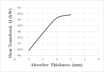 | Figure 6. Effect of absorber thickness on heat transfer |
4. Conclusions
From the simulation analysis of absorber-fin assembly for solar photo-voltaic applications, following conclusions are drawn.● Copper is found to be most suitable material to absorb and transfer the heat from the solar cell. Considering the material density and economic viability, aluminium may also be taken as a candidate material. ● Fins of smaller length resulted in lower thermal gradients in the absorber contributing to increased heat extraction and thermal efficiency of fins.● For the constant fin exposure area, increase in fin spacing resulted in drop of heat transfer from the fins.● Use of thinner fins resulted in significant improvement in heat transfer and effectiveness.● Lower absorber thickness yielded enhanced heat transfer by fins.
References
| [1] | Rakesh Kumar and Marc A. Rosen, 2011, A critical review of photovoltaic–thermal solar collectors for air heating, Applied Energy, 88, 3603–3614. |
| [2] | Chow T.T., 2010, A review on photovoltaic/thermal hybrid solar technology, Applied Energy, 87, 365–379. |
| [3] | Arif Hasan M. and Sumathy K., 2010, Photovoltaic Thermal Module Concepts and their Performance Analysis: A Review, Renewable and Sustainable Energy Reviews, 14, 1845-1859. |
| [4] | Tiwari G.N., Mishra R.K. and Solanki S.C., 2011, Photovoltaic modules and their applications: A review on thermal modeling, Applied Energy 88, 2287–2304. |
| [5] | Soteris A. Kalogirou, 2004, Solar thermal collectors and applications, Progress in Energy and Combustion Science, 30, 231–295. |
| [6] | Tripanagnostopoulos Y., Souliotis M., Battisti R. and Corrado A., 2005, Energy, Cost and LCA Results of PV and Hybrid PV/T Solar Systems, Prog. Photovolt: Res. Appl. 13, 235–250. |
| [7] | Donald Craig, “Extensible Hierarchical Object-Oriented Logic Simulation with an Adaptable Graphical User Interface”, M. S. thesis, Memorial University of Newfoundland, St. John's Newfoundland, July 1996. |
| [8] | ANSYS Mechanical APDL Introductory Tutorials, Release 15.0, November 2013. |
| [9] | Kothandaraman C. P., Heat and Mass Transfer Data Book, New Age International, 2004. |
| [10] | Yunus A. Çengel, Heat Transfer: A Practical Approach McGraw-Hill, 2003. |
 Abstract
 Reference
 Full-Text PDF
 Full-text HTML