-
Paper Information
- Next Paper
- Previous Paper
- Paper Submission
-
Journal Information
- About This Journal
- Editorial Board
- Current Issue
- Archive
- Author Guidelines
- Contact Us
Journal of Mechanical Engineering and Automation
p-ISSN: 2163-2405 e-ISSN: 2163-2413
2015; 5(3A): 12-18
doi:10.5923/c.jmea.201501.03
Numerical Study on the Imbalanced Flue Gas Temperature at Boiler Rear Pass Area of a Tangential-Fired Coal Power Plant
 Abstract
 Reference
 Full-Text PDF
 Full-text HTML
A. Ahmad1, H. Hasan1, M. Kannan2, N. A. W. M. Noor1, M. T. Lim1
1TNB Research Sdn. Bhd.
2Universiti Tenaga Nasional
Correspondence to: A. Ahmad, TNB Research Sdn. Bhd..
| Email: |  |
Copyright © 2015 Scientific & Academic Publishing. All Rights Reserved.
This work presents the numerical study on the boiler temperature stability on a tangentially-fired 700MW coal power plant. The prime objective of the project is to identify the causes of imbalance flue gas temperature at boiler rear pass and to recommend the appropriate solutions to the problem. In order to achieve the objective, technical analysis utilizing the Computational Fluid Dynamics (CFD) simulation techniques was undertaken to simulate the combustion process, the combustion gas flow pattern and temperature distributions inside the boiler. The effects that were investigated were the effect of change in nozzle tilt angle and the effect of combustion using different coal types. The results of the baseline case indicate that the flow inside the furnace is very complex with intense mixing. The flow is highly swirling in anti-clockwise direction and the pattern persists until the exit of the boiler. Even with the design settings, the temperature distribution prior to the entry to the superheater is not symmetrical. The results show that that the uneven temperature distribution at upper furnace elevation exists regardless of the type of fuel used. It is suggested that the high gas temperature at furnace rear pass could be alleviated by operating at low tilt angle of the burner nozzle.
Keywords: Numerical study, Temperature stability, Coal, Rear pass area, Tilt angle
Cite this paper: A. Ahmad, H. Hasan, M. Kannan, N. A. W. M. Noor, M. T. Lim, Numerical Study on the Imbalanced Flue Gas Temperature at Boiler Rear Pass Area of a Tangential-Fired Coal Power Plant, Journal of Mechanical Engineering and Automation, Vol. 5 No. 3A, 2015, pp. 12-18. doi: 10.5923/c.jmea.201501.03.
Article Outline
1. Introduction
- Steam generator plays an important element in most of the thermal power plant in the world today. The generation of steam in boiler normally requires huge amount of heat which is produced by burning fossil fuel. With the recent trend in the increase of fossil fuel price in the world, careful steps are taken by most of the boiler operators to optimize the use of these fuels and to find alternatives that could replace the fossil fuel. Despite some advancement made in the use of alternative energy source, e.g. renewable energy, it cannot totally replace the fact that the use of fossil fuel still can be considered significant at least in a few decades to come. In the open literatures, works on the study of combustion behaviour inside a boiler furnace were abundance. They can be broken down into several classifications in terms of the objectives such as to investigate the NOx emission e.g. [1–4], general combustion behaviour inside pilot or full scale furnace e.g. [5–9], investigation on the effect of boiler operating parameters e.g. [10, 11], CFD study to investigate the formation of fouling and slagging in furnace [12] and etc. However, the majority of these works concentrated on pilot scale or full scale boilers utilizing coal as the main source of fuel. Research on coal combustion in boiler furnace becomes the central attention among the scientist working in similar field probably due to the complexity of the combustion behaviour of the fuel that requires detail understanding on the processes and mechanism during the combustion. In addition, more attentions were given to the coal combustion study as compared to other fuel was due to the maximum utilization of coal in most of the countries around the world. This leads to very little attention given towards the study of other combustion in boiler furnace firing different fuel such as light and heavy fuel oil as well as natural gas. Tangential fired boiler is widely adopted by most of the boiler operators due to its many advantages especially when large capacity boiler is desirable. Among the most distinct advantages of this type of boiler is the ability to distribute heat evenly throughout the water wall. Despite this advantage, the existence of residual swirl in tangential-type boiler has created problem and if this problem is ignored, it could lead to the build-up of thermal stress in particular on the upper furnace which in turn, could cause boiler tube failure.Effort to study the flow characteristics in particular the temperature imbalance in tangential fired furnace has been carried out many years ago but little progress was made in understanding this mechanism. This is especially true when the boiler is oil or gas-fired at which the average combustion gas temperature is higher than those of coal-fired boiler. Nevertheless, the earlier works carried-out by a few workers have opened-up wide opportunity for others to further investigate the phenomenon deemed to exist in almost all tangential fired furnace [13–16]. The imbalance temperature carried away to rear pass of the boiler has tremendous effect on the structural integrity of the boiler tubes and the boiler efficiency. The main culprit for the unbalance temperature at rear pass was predicted to be the burner angle setting. This paper investigates the phenomenon of the rear pass temperature profile with design and off-design conditions. Then, the solution to the current rear pass temperature problem is addressed.
1.1. Brief Description of the Boiler under Study
- The 700MW boiler is shown in Fig. 1.
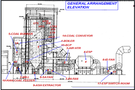 | Figure 1. 700MW boiler general arrangement |
1.2. Problem Statement and Scope of Study
- A reheater is a component of a coal fired power plant boiler which is responsible to reheat the steam known as cold reheat which is exiting the high pressure turbine. After being reheated, it is sent back to the second steam turbine. This reheater has boiler tubes placed in panels. While this process is going on, it was identified that there are uneven temperature distribution in the re-heater. This uneven temperature distribution can cause heat to be concentrated only on a certain region at the boiler tubes causing the tube to have temperature differences. When the temperatures are different along the tubes, it will cause irregular expansion processes which will lead to cracking in the boiler tubes of the reheater. Crack in boiler tubes will reduce the efficiency of the boiler system.The purpose of this project is to find a solution to reduce the uneven temperature distributions in the left and right-hand side of the reheater of a 700 MW boiler. The fluid that was being studied in this project was the flue gas. Flue gas or also known as combustion exhaust gas which is exiting to the atmosphere via a flue, which is a pipe or channel for conveying exhaust gases from a furnace, boiler or steam generator. Its composition usually consists of mostly nitrogen derived from the combustion of air, carbon dioxide, and water vapour as well as excess oxygen. It further contains a small percentage of a number of pollutants, such as particulate matter (like soot), carbon monoxide, nitrogen oxides, and sulphur oxides. The first CFD simulation was done for the existing plant operation in terms of the fuel and air flow configurations by using 3-dimensional CFD simulation. Once the simulation for the existing plant operation was done, then it was followed by testing on a few boiler parameters such as the effect of tilt angle on temperature distribution inside the furnace. Data from both the simulations was recorded and compared with the measured data.The results gained in this investigation are useful to gain insight into the behaviour of combustion temperature and velocity in particular the formation of un-even gas temperature at the upper furnace. The optimum operating condition to alleviate the problem of un-even and excessive gas temperature at furnace rear pass was also be determined based on the extensive simulations on boiler tilt angles.
2. Methodology
2.1. Model Development
- The boiler was modelled based on the detail manufacturer's drawing provided by the operator. Some simplifications were made on a few components of the furnace where detail dimensions were absent. In this study, detail dimension of the coal burners were not taken into account since detail flow study within and close to the burner regions were not needed. On top of that, the contour of water wall was assumed to be flat but in reality, the water wall consists of an array of horizontal pipes with complex surface curvature. The simplifications on complex geometry were necessary to avoid complex meshing which could cause divergence in the solution. These simplifications were applied to extreme regions with minor assumptions where the flow properties are not critical. This would not affect the final solutions of the flow and combustion characteristics in the furnace as the ultimate aim of this work is to predict the combustion gas flow and temperature profile at the boiler rear pass.The 3D view diagram of the furnace is illustrated in Figure 2.
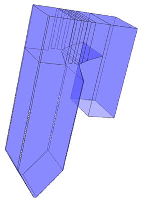 | Figure 2. 3D view of the furnace model |
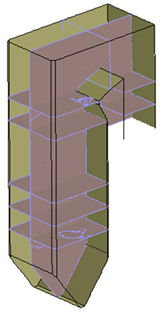 | Figure 3. Planes at different x, y and z-direction for analysis |
2.2. Mesh Generation
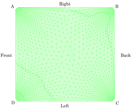
- Generating a good mesh for flow and combustion calculation is extremely important to ensure sufficient solution accuracy. A combination of structured and unstructured grid was adopted in this investigation and this is shown in Figure 4. Higher mesh concentration was applied in the windbox region where fuel and air are injected for combustion, creating imaginary fireball at furnace centre that distribute heat evenly throughout the water walls. Due to its tangential firing system, intense swirl was anticipated at the furnace centre, thus careful attention was given towards the mesh scheme to resolve the swirl flows. Figure 5 shows the mesh scheme at the coal injection plane with high mesh concentration applied near the coal injection points. For the purpose of analysis, the four injection corners were named as A, B, C and D while the front, rear, left and right furnace sides were also labelled in the figure.
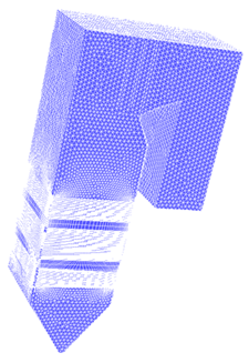 | Figure 4. Mesh scheme of the furnace |
 | Figure 5. Detail mesh at coal injection plane |
|
3. Results and Discussion
3.1. Temperature Profiles at Furnace Rear Pass
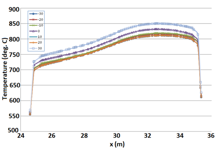
- In order to specifically investigate the detail of temperature distribution at furnace rear pass, plots of temperature between the left and right hand side of the furnace were generated. Figure 6 shows the gas temperature distribution at furnace rear pass for different tilt angles. The general trend of temperature profile for all tilt angles shows similar pattern. It is clear that the right hand side shows higher gas temperature as compared to the left hand side with approximate difference of 100-150ºC. The highest temperature magnitude is given by tilt +30º while the lowest gas temperature is given by negative tilts (in this case -20º).
 | Figure 6. Temperature distribution at furnace rear pass (from left to right sides) |
3.2. Rear Pass Temperature Profile at Different Tilt Angles
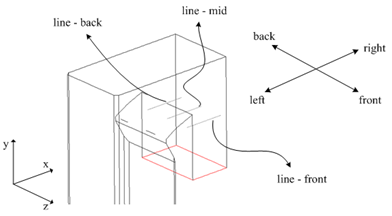
- In order to investigate the temperature profile details at the boiler rear pass, plots of temperature against distance is made in the regions. Three lines are created at the rear pass where the plot was made and this is shown in Figure 7. The three lines were named line-back, line-mid and line-front to indicate the locations where the temperature plots were made respectively. The plots were made at constant furnace elevation (rear pass elevation) while variation was made along x (left to right) and z-axis (note: z-axis indicates the back, mid and front side of the furnace)
 | Figure 7. Schematic diagram of the location of line profile at boiler rear pass for analysis |
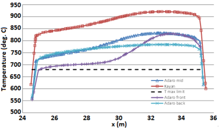 | Figure 8. Temperature distribution at furnace rear pass for Adaro and Kayan coal combustion |
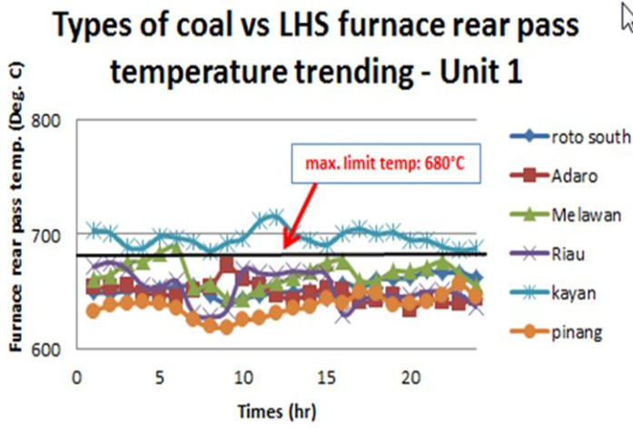 | Figure 9. Gas temperature at LHS furnace rear pass temperature against time |
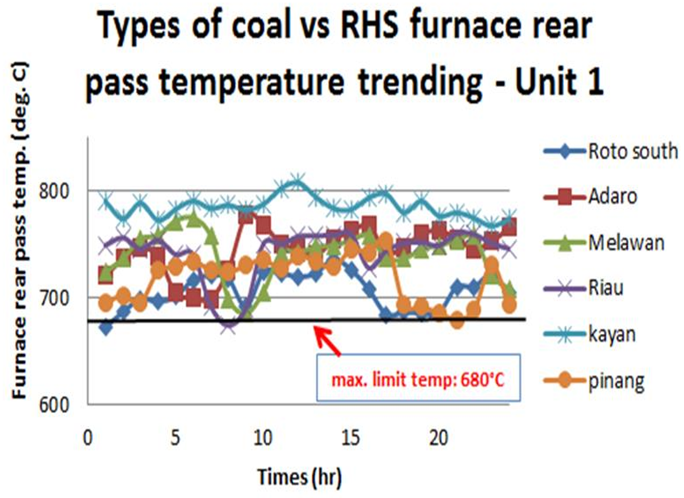 | Figure 10. Gas temperature at RHS furnace rear pass temperature against time |
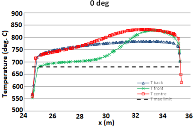 | Figure 11. Temperature profile at furnace rear pass taken at centre, back and front boiler sides |
4. Conclusions and Recommendations
- Based on the simulation results obtained, the following conclusions can be withdrawn:• Specifically, the trend shows that the furnace RHS temperature is always higher than LHS. However, the magnitude differs with tilt angle.• The overall temperature magnitude predicted by the simulation show higher temperature magnitude compared to the measured data. This can be attributed to the simplification made to the simulation model which ignores the physical body of superheater and reheater platens at furnace top. However, in the simulation, it was assumed that the heat absorption rate of these platens are transferred to the heat rate by the water walls. This heat transfer rate was obtained based on trial and error due to insufficient data provided by the station. Despite the higher gas temperature predicted, the trend for all cases were found to be in good agreement with measure data.• The flow inside the furnace is highly swirling due to the effect of tangential firing system, indicating good mixing of coal particles and air. The temperature distribution at main combustion zone (windbox region) is initially symmetry in shape and the formation of fireball is right at the centre of the furnace. As hot flue gas flows upwards, the symmetricity of the temperature distribution is slightly off-centred as the fireball location shifted upon passing the furnace nose at higher elevation. This causes the temperature difference between the left and right hand side of the furnace.• The temperature difference, (ΔT) between the left and the right hand-side of the furnace was also found to differ as furnace elevation increases. For the baseline case (tilt at 0°), the ΔT is approximately 80°C between RHS and LHS. Other tilt angle conditions also give more or less similar temperature difference magnitude. The highest ΔT is recorded for tilt angle of +30° at approximately 100°C. Whereas, the lowest predicted at -20°tilt angle with ΔT magnitude of only 60°C. Based on the major findings obtained from the simulation and validated data by measurement taken on-site, it is recommended that the station operates at minimum tilt angle (preferably -20º) to reduce the gas temperature at furnace rear pass. Even though this method does not eliminate the temperature variation between the left and right side of the furnace, this setting is predicted to give the minimum gas temperature at furnace rear pass compared to other tilt angle setting.