H. Hassan, M. T. Lim, A. Ahmad, H. A. Hamid, N. M. Noor
TNB Research Sdn Bhd.
Correspondence to: H. Hassan, TNB Research Sdn Bhd..
| Email: |  |
Copyright © 2015 Scientific & Academic Publishing. All Rights Reserved.
Abstract
A solid fuel combustion testing rig facility is an ideal tool to simulate solid fuel combustion and related phenomena at a meaningful scale. The design, fabricate and construction of the solid fuel combustion test rig facility (SFCTRF) was developed by TNB Research Combustion Group started in May 2014 and the rig was successfully commissioned in November 2014. In this paper, for the combustion tests, two (2) coal were used, which were Coal A and Coal B (sub-bituminous coal). These two coal were successfully tested in the combustion test rig. The tests were carried out to determine their performance in terms of flame stability, furnace temperature profile and fouling ash deposit appearance. The results emanating from this research has shown that the solid fuel combustion test rig facility (SFCTRF) is an effective tool for the evaluating and characterising coal combustion performance on a quantitative basis.
Keywords:
Design, Test rig, Flame stability, Combustion performance
Cite this paper: H. Hassan, M. T. Lim, A. Ahmad, H. A. Hamid, N. M. Noor, Development of a Solid Fuel Testing Rig Facility for Research in Coal Combustion Performance, Journal of Mechanical Engineering and Automation, Vol. 5 No. 3A, 2015, pp. 6-11. doi: 10.5923/c.jmea.201501.02.
1. Introduction
The current practice for TNB coal power plants is that all new coal types which have not been fired in TNB plants are required to undergo coal combustion trial directly in the boiler at the plant where the coal assignment should be sent. Most of the time the trial burnt is carried out while the unit is at the normal operating condition. Any disturbances on the combustion and the emission will jeopardise the unit as well as the grid system stability. As a result of this practice, the many of plant components will be degraded, which will eventually affect the overall plant performance, especially if the coal is not suitable to be fired in the particular boiler. One of the major issues found during the combustion trail burn is slagging and fouling. The combustion of coal and other solid fuels in a power plant causes build-up of combustion deposits such as soot, ash and slag on the boiler’s heat transfer surface. The coal ash constituents affect the propensity of the ash to slagging and fouling. The occurrence of slagging if left unchecked and controlled may cause severe disruption to the heat distribution in the boiler and may ultimately disrupt the operation of the plant. A solid fuel combustion test rig facility is an ideal tool to simulate solid fuel combustion and related phenomena at a meaningful scale. The design, fabricate and construction of the solid fuel combustion test rig facility (SFCTRF) started in May 2014 and successfully commissioned in November 2014. The combustion test rig facility was incorporated with measurements device such as suction pyrometer, radiometer and carbon burnout. There are 19 (nineteen) thermocouples installed in the main reactor zone to measure the temperature profiles. For the combustion tests, two (2) coal were used, which were Coal A and Coal B. These two coal were successfully tested in the combustion test rig. The tests were carried out to determine their performance in terms of flame stability, furnace temperature profiles and fouling.The results emanating from this research has shown that the solid fuel combustion test rig facility (SFCTRF) is an effective tool for the evaluating and characterising coal combustion performance on a quantitative basis.
2. Design Development of Combustion Test Rig Facility
In order to design the combustion testing rig facility, several factors were considered, such as the type of fuel that will be used as the feedstock, existing design available and plant location. These are described in the following subsections.
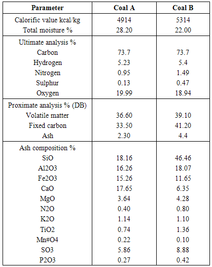
2.1. Coal Feedstock
For this study, Coal A and Coal B coal (sub-bituminous coal) were used. Both coal are form Indonesia. Table 1 shows the fuel analysis of caloric value, ultimate, proximate analysis and ash composition for Coal A and Coal B.Table 1. Fuel analysis for coal A and Coal B
 |
| |
|
2.2. Design Specification
The specification is to design, fabricate, supply of all materials, appliances, labour and necessary incidentals for the complete installation and handing-over in approved working order, warranty and maintenance thereafter during the period of defect liability of aforesaid solid fuel combustion test rig facility (SFCTRF). This SFCTRF shall include the following physical features, which shall include:i. Burner and coal preparation systemii. Furnace and air handling systemiii. Measuring equipment systemiv. Control instrumentation and data acquisition systemv. Other related work such as platforms, supports,
2.3. Technical Drawing for the Design of Solid Fuel Combustion Test Rig Facility
The figures 1 illustrate the solid fuel combustion test rig facility isometric views.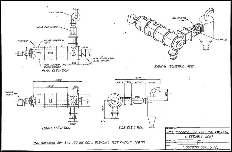 | Figure 1. Solid fuel combustion test rig facility (Isometric view) |
2.4. Furnace Design of Solid Fuel Combustion Test Rig Facility
The figures 2 and figure 3, show the furnace technical design exploded view and technical drawing for the design of solid fuel combustion rig facility respectively.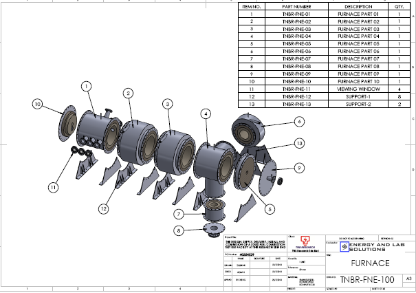 | Figure 2. Furnace design exploded view |
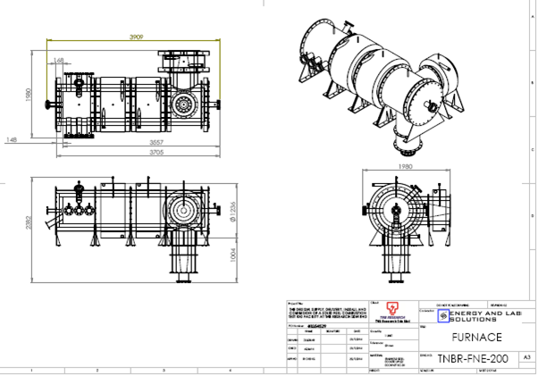 | Figure 3. Furnace technical drawing |
2.5. Design, Fabrication and Completion of a Solid Fuel Combustion Test Rig Facility
The design, fabricates, supply, deliver, install, testing and commissioning of solid fuel combustion test rig facility started on 7th may 2014. The scope of works were divided into two sectors which are (i) Building extension from existing gasification pilot plant building and (ii) solid fuel combustion test rig facility.The building extension and solid fuel combustion test rig facility installation was completed at the end of November 2014. The testing and commissioning of the solid fuel combustion test rig facility was carried out on 20th—30th November 2014.Figure 4 shows the completion of solid fuel combustion test rig facility.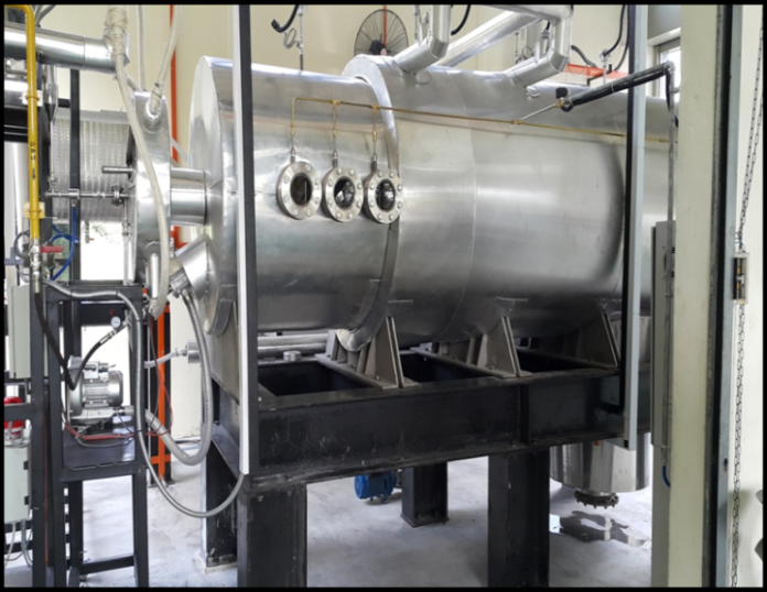 | Figure 4. Completion of combustion test rig facility |
3. Result and discussion
3.1. Features of the Test Furnace
The test furnace is of the horizontal L-shaped type with the inner walls of the furnace is been refractory and is extensively ported for detailed combustion and radiation testing. The furnace is divided into 4 modular sections with the total length 3.9 meter and the internal diameter is 0.6 meter. The furnace operation temperature was ranges between 1000- 1400°C. It is also fitted with 10 fouling probes with variable cooling water jackets. The fouling probes collect ash deposits for measurement of emissivity. In this studies, combustion test of the following type are performed in the furnace:i. Measurement of relative ignitability.ii. Measurement of furnace temperature profile, probing along the access of the flame to determine temperature as a function of furnace distanceiii. Measurement of total radiation and flame emissivity along the furnace. Similar studies conductor by ACIRL in Australia which using similar type of furnace horizontal L-shape but difference configuration [1] and [2]. Rajoo P. conducts study on comparison of pulverised fuel burnout and gaseous using pilot Scale Combustion Test Rig Facility. The results also show that the pilot scale can evaluate and characterise coal combustion on quantitative basis [3].
3.2. Furnace Temperature Profiles of Solid Fuel Combustion Test Rig Facility
The identified samples for the combustion test were Coal A and Coal B (sub-bituminous coal).This test determines the conditions under which a stable flame is produced. For this purpose a stable flame is defined as one which is attached to burner quarl. In performing this test the burner swirl setting, coal type and air flows were adjusted and the flame was observed visually to be stabled was produced.The temperature profiles, measured through measurement ports, position of thermocouples (TC1–TC4), were plotted against time, and are shown in Figure 5 and figure 6 for Coal A and Coal B respectively. Several test runs were performed during the commissioning and testing.The trends found were consistent with the 2 experiments of Coal A and Coal B i.e., run Coal A (TC1=805°C), (TC2=659°C), (TC3=593°C), (TC4=596°C) and run Coal B (TC1=806°C), (TC2=677°C), (TC3=597°C), (TC4=596°C for low and high temperature experiments, respectively. The initial fluctuations (during 0–360 min), shown in Figure 5 and Figure 6, were caused by adjusting the fuel flow to match the required combustion temperature (≈800°C). After approaching a steady state, the data in the figures showed that the first thermocouple (TC1) had an average peak-temperature of 800°C. 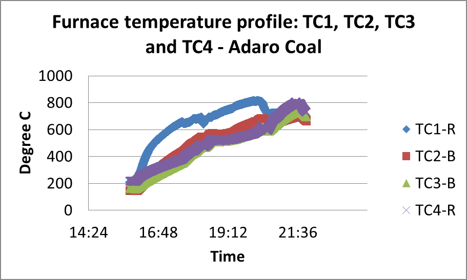 | Figure 5. Furnace temperature profiles for Coal A |
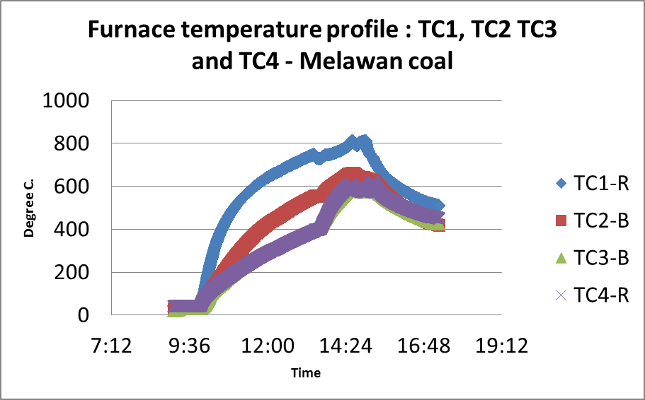 | Figure 6. Furnace temperature profiles for Coal B |
Under condition of zero swirl an axial flame was produced in which the coal jet was clearly visible and the flame was detached from the burner. The Figures 7 and figure 8 show Adaro coal’ ignitibility front view and side view respectively.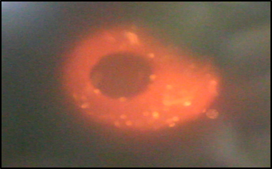 | Figure 7. Coal A ignitibility front view |
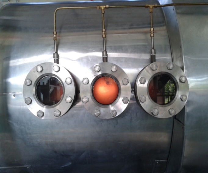 | Figure 8. Coal A ignitibility front view and side view |
3.3. Fouling Analysis (Convection Section Deposits)
The deposit formation on specially designed probes were characterised as a function of firing rate and flue gas temperature as a method of evaluating fouling potential. The fouling probes are located in the high temperature post radiant section gas stream. At the termination of procedure, which lasted about 6-8 hours, the furnace was stopped operation and allowed to cool. The probes bank were than removed and the nature of deposit built up were examined. Figures 9 and figure 10 show photographs of the deposits of Coal A and Coal B on the test section of the deposition probe, after eight hours of exposure time respectively. It is observed a relatively homogeneous layer that can easily remove and similar to the deposit layer obtained for the Coal B (Figure 10). In none of the two tests were observed the sintering of the material, common at high temperatures and after long exposure times of the surfaces.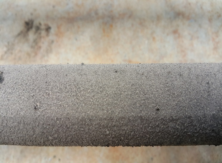 | Figures 9. Photographs of the deposits of Coal A |
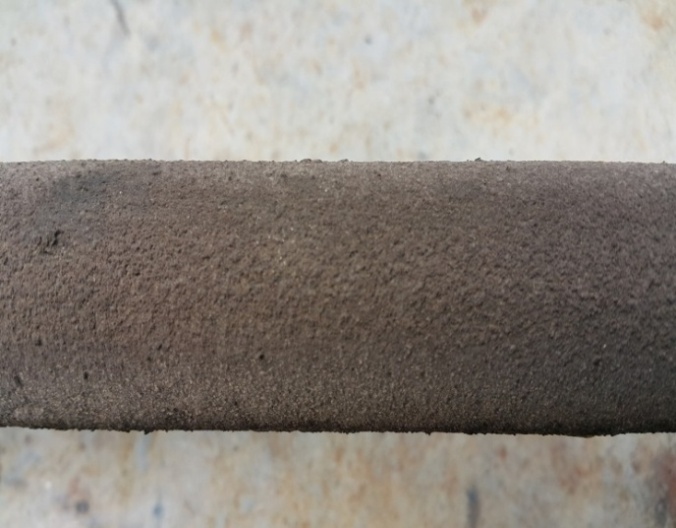 | Figures 10. Photographs of the deposits of Coal B |
4. Conclusions
The results emanating from this research has shown that the solid fuel combustion test rig facility (SFCTRF) is an effective tool for the evaluating and characterising coal combustion performance on a quantitative basis. Validation of more testing such as carbon burnout, size particles, radiant heat flux, ash deposit and residue are required to increase the degree of confidence in the SFCTRF results and understanding the impact of the full-scale boiler configurations. A quantitative methodology for the gaseous emission will be further investigated.
ACKNOWLEDGEMENTS
The author would like to thank the Tenaga Nasional Berhad, for funding this research project under TNBR/RD 119/2013 (R-G-RD-0119-13-025-1).
References
| [1] | J. Baker, P. Bennett, D. Holcombe, P. Nayor. Australian Coal Industry Research Laboratories Ltd. Construction and calibration of the Australian coal combustion testing and research activity. July 1986. |
| [2] | S. Su, H. Jone, D. Holcombe. Fouling propensities of blended coals in pulverised coal-fired power station boiler. Fuel 82 page 1653-1667. |
| [3] | P. Rajoo. The application of pilot scale coal evaluation to full scale boiler. Degree of Master of Science in Engineering to the University of Witwatersrand, Johannesburg. 2010. |
 Abstract
 Reference
 Full-Text PDF
 Full-text HTML