-
Paper Information
- Next Paper
- Previous Paper
- Paper Submission
-
Journal Information
- About This Journal
- Editorial Board
- Current Issue
- Archive
- Author Guidelines
- Contact Us
Journal of Civil Engineering Research
p-ISSN: 2163-2316 e-ISSN: 2163-2340
2014; 4(3A): 191-202
doi:10.5923/c.jce.201402.33
The Use of Steel Damper for Enhancing the Seismic Performance of R/C Frame with Soft First Story
 Abstract
 Reference
 Full-Text PDF
 Full-text HTML
Daniel R. Teruna1, Taksiah A. Majid2, Bambang Budiono3
1School of Civil Engineering, Universiti Sains Malaysia, Penang, Malaysia
2Disaster Research Nexus, School of Civil Engineering, Universiti Sains Malaysia, Penang, Malaysia
3Department of Civil Engineering, Institute of Teknologi Bandung, Bandung, Indonesia
Correspondence to: Daniel R. Teruna, School of Civil Engineering, Universiti Sains Malaysia, Penang, Malaysia.
| Email: |  |
Copyright © 2014 Scientific & Academic Publishing. All Rights Reserved.
The responses of reinforced concrete frame building having soft first story under three selected earthquakes record is presented. The soft first story is characterized by the open space on the ground floor, while the story above having infill walls. In order to improve the seismic responses of r/c frame building, the steel damper of flexural type are installed into building on the first story. The finite element method is employed to simulate the response of the frame building subjected to selected severe earthquakes using non-linear time history analysis. The equivalent three strut model is adopted to account the interaction of masonry infill with structure members on building responses, and the presence of the opening in reduction both stiffness and strength of the masonry infill are also considered. The simplified tri-linear model of stress–strain relationship is applied to account for the nonlinearity of the equivalent strut material, while hysteretic behavior of steel damper approximated by a bilinear model. In addition, the inelastic behavior of beam and column elements with rigid end zone is also adopted. Furthermore, the results are obtained from nonlinear analysis to be used for comparison the seismic performance of the building under consideration. Finally, it was clearly noticed that the use of steel damper not only to avoid the premature collapse of building but also to increase the seismic performance of the soft first story buildings significantly.
Keywords: Steel damper, Soft story, Strut model, Infill wall, Seismic performance
Cite this paper: Daniel R. Teruna, Taksiah A. Majid, Bambang Budiono, The Use of Steel Damper for Enhancing the Seismic Performance of R/C Frame with Soft First Story, Journal of Civil Engineering Research, Vol. 4 No. 3A, 2014, pp. 191-202. doi: 10.5923/c.jce.201402.33.
Article Outline
1. Introduction
- The absence of infill wall on the first story cause significant changes of the story stiffness under consideration, and may lead to damage or collapse due to soft first story mechanism formed. Figure 1. presents examples of buildings with first soft story having a poor performance during past earthquakes. However, these similar buildings is being adopted among architects, because these buildings offer open space which usually intended for lobby, parking or retail store. According to FEMA 451-B [7] that structures having soft story shall be designated as having vertical structural irregularity. The building is said having soft story when the lateral stiffness is less than 70 percent of that in the story above or less than 80 percent of the average lateral stiffness of the three stories above. A building are categorized as extreme soft story If its posses the lateral stiffness is less than 60 percent of that in the story above or less than 70 percent of the average lateral stiffness of the three stories above.
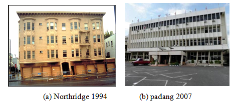 | Figure 1. Examples of soft first story mechanism & collapse |
2. Modeling of Infill Masonry Wall
2.1. Determination of the Equivalent Strut Width
- The behavior of infilled frame under lateral loads was investigated by Ateris [2] using finite element method. It was observed that the contact length between the infill and the frame members are varied, and the frame’s contribution to the overall stiffness is influenced by change in its mode of distortion. Figure 2 shows the general behavior infilled frame under lateral load.
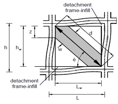 | Figure 2. Masonry infill frame sub-assemblage [2] |
 | (1) |
 | (2) |
 is the diagonal length of the masonry panel,
  is the column height,
  is the modulus of elasticity of the masonry panel,
  is the thickness of the masonry panel,
  is the flexural rigidity of the column,
  is the height of the masonry panel,
  is angle of the inclination of the diagonal strut with horizontal line. The increasing lateral loads will reduce the length of the contact between masonry infill wall with r/c frame. Park and Paulay [12] proposed the contact length of between infill wall and column or beam as
  | (3) |
2.2. Three - Strut Model of Infill Wall
- In the 3-strut model, the masonry infill wall replaced by 3-equivalent pin-jointed diagonal strut having the same thickness as infill wall and having equivalent width as defined in Eq.(1). The joint of strut and beam and column members are presented in figure 3.
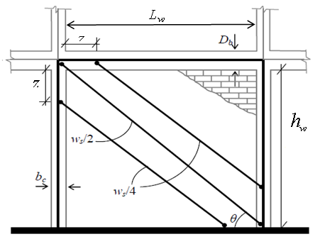 | Figure 3. Three-strut model for masonry infill wall [10] |
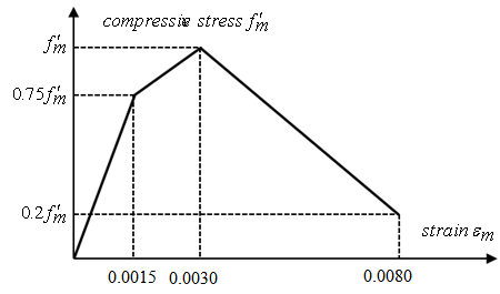 | Figure 4. Tri-linear stress-strain model for masonry brick |
2.3. Effect of Opening on the Lateral Stiffness
- Although, it was clearly noticed that the infills play a role in increasing the lateral stiffness of complete structure, the past experience have proved that partially infilled frame structures showed poor behaviour during earthquakes event. Additionally, the increase in the opening percentage lead to a decrease on the lateral stiffness of infilled frame [2, 14]. Thus, the presence of infills opening will influence the whole seismic behavior infilled frame structure.The effect of opening on the lateral stiffness have been proposed by Asteris [2] through parametric study using finite element method. The stiffness reduction factor is given by
 | (4) |
 is the ratio of the area of opening to the area of infill wall. Furthermore, when calculate the strength of infill wall with opening, the strength reduction factor assume equal to the stiffness reduction factor.
3. Steel Damper
3.1. Displacement Dependent Damper
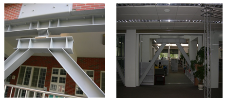 | Figure 5. Two examples of strengthening building with steel yielding damper (Courtesy by Earthquake Proof System) |
3.2. Basic Characteristic of Steel Damper
- A good damper must posses a stable and large hysteretic curve through a yielding of steel plate. In order to do so, a damper must have a large rotational capacity when its deformed inelastic range. Figure 6 shows a plastic mechanism for a single story frame incorporating a damper elements mounted at the top chevron bracing. The plastic rotational demand (
 ) can be estimated from equation 5.
 | (5) |
 is the plastic story drift angle.
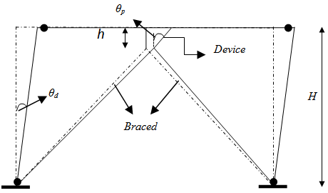 | Figure 6. Deformation mechanism of a single story of frame with damper elements |
 | (6) |
 | (7) |
 | Figure 7. Nonlinier modeling of restoring force frame and damper |
3.3. Modeling of Steel Damper
- The primary factor affecting damper elements are elastic stiffness (Ke), yield displacement (dy), and yiel force (Py) as reported by Whittaker et al [18]. Therefore, a bilinier model is appropriate to represent of damper device inelastic behavior as depicted in figure 8. The hysteretic energy is dissipated of device in one cycle can be determined from equation 8.
 | (8) |
 is ratio of elastic stiffness to plastic stiffness of the device.
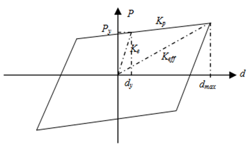 | Figure 8. Bilinier modeling of device |
4. Energy Based Damage Index
- In recent years, energy based approach are often used in earthquake resistant structures design [4]. In order to quantify performance of a structures during earthquake, drift and damage index are commonly accepted as performance criteria. Damage index model based on cumulative plastic deformation and maximum hysteretic energy demand has been developed by several researcher, such as [3, 12, 20]. In this paper, damage index model are proposed by Park and Ang [12] are employed to investigate the damage level of the building with and without damper under three series selected ground motion. Park and Ang damage index as a linear combination of the damage caused by maximum deformation and that contributed cyclic loading effect. In term of damage index can be expressed as
 | (9) |
 is constant to account the effect of cyclic load and structural properties; ranges from 0.05-0.15, Ei is hysteretic energy demand at
  plastic hinge, and
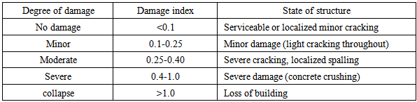
  is number of plastic hinges. In this context, the interpretation between damage level and damage index as listed in table 1.
|
5. Numerical Study
5.1. Building Description
- The elevation four story r/c building with open story at the ground floor and masonry infill walls in the other story are shown in figure 9. Figure 10 present the strengthening of the structure using yielding damper. The window opening is 1mx1.5m. Design parameters for the structure are summarized as - Concrete strength:
 - Reinforcement steel :
  - Masonry wall:
  - Dead load: 40kN/m (1-3 floor); 30kN/m (roof).- Live load: 15kN/m (1-3 floor); 12kN/m (roof).- Columns size are 400mm x 400mm with the following reinforcement: 16 Ø16mm for 1st and 2nd story (designated as column type1; 12 Ø16mm for 3nd and 4nd story (designated as column type2. - Beams size are 300mm x 500mm (1-3 floor) with the following reinforcement: top (5 Ø16mm), bottom (3 Ø16mm) and designated as beam type 1.- beams dimension for the top floor are 250mm x 500mm with reinforcement: top (4 Ø16mm), bottom (3 Ø16mm), and designated as beam type 2.
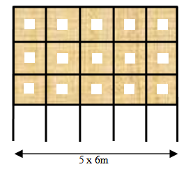 | Figure 9. 4-story of concrete frame |
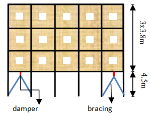 | Figure 10. 4-story of concrete frame with steel damper |
5.2. Structural Analysis and Modeling
- Finite element analysis of the frame were performed using PERFORM-3D software under 3 (three) acceleration records, i.e. El-Centro, San-Fernando and Tabas scaled to 0.5g. All beams, columns and braces were modeled as one dimensional element. Beam and column elements were modeled as an elastic segment with distributed plastic hinge and rigid end zone element as depicted in figure 11 and 12. The rigid end zone was selected a half of column width for beam element and a half of beam width for column element. Beams are usually have small axial forces and bent in only one plane, so that moment-curvature relationship was applied to account the inelastic behavior of the beam element. Additionally, columns are usually have large axial forces and bent in biaxial plane, so that is necessary to account for PMM interaction. In the dynamic analysis, Rayleigh damping was constructed, so that the damping ratio is close to 5% over a range of periods from 0.2T1 to T1, where T1 is the first mode period. Furthermore, in order to limit inter-story drift to less than 1%, by adding steel damper with SR=12, yield strength, 900 kN, Ke=360kN/mm, and 1% post yield stiffness ratio. The plastic hinge length is given as recommended by Park and Paulay [11]:
 | (10) |
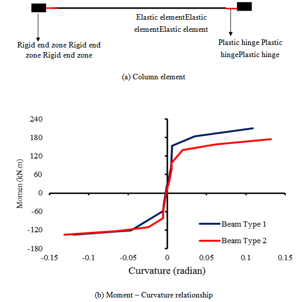 | Figure 11. Beam element modeling |
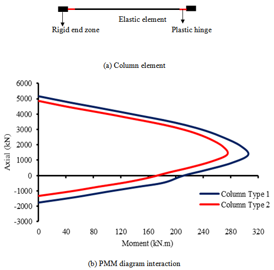 | Figure 12. Column modeling |
|
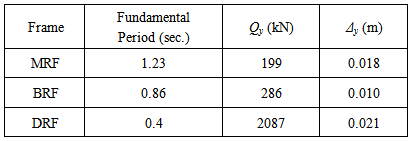
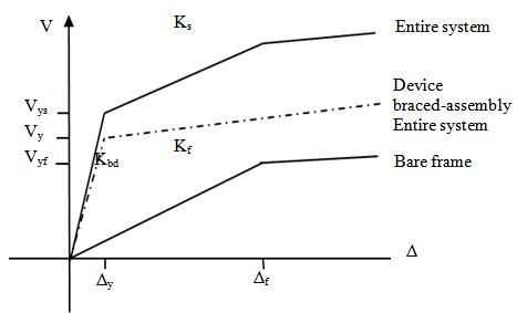
 | Figure 13. Evaluation of Qy and Δy from capacity curve |
6. Results and Discussion
6.1. Inter-story Drift
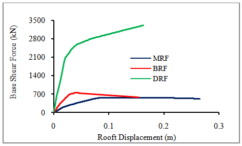
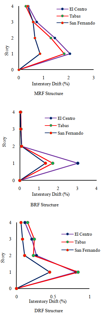
- Inter-story drift is one of the response parameters that are widely used in determining the seismic performance of a structure subjected to ground motion. Figure 14 shows the comparison inter-story drift of MRF, BRF and DRF under 3 selected scaled ground motion. It was noted that inter-story drift on the first story higher than others story due to soft story effect. Additionally, the effect of infill walls also increases the inter-story drift on the first story except for Tabas earthquake. In contrast, the present infill walls reduce inter-story drift on the others story significantly due to effect of added stiffness. The improvement of the seismic performance using steel damper on the first story can be observed through DRF frame. The inter-story drift on the first story reduced significantly below 1% as targeted because of the effect of added damping and stiffness. It was also observed that the maximum inter-story drift occurred under input motion of El-Centro, followed by Tabas, and San Fernando. Furthermore, the earthquake characteristic influence the interstory drift of the structures as shown in Figure 15. It was observed that for MRF and BRF structures, the smallest interstory drift occurred due to San Fernando earthquake followed by Tabas and El-Centro earthquake. However, for DRF structure, the effect of Tabas earthquake and El-Centro earthquake almost the same. It can be noticed that for soft first story structure is characterized by large drift concentrated on the first story, while upper story behave as rigid body. This behaviour can be demonstrated through BRF frame where inter-story drift above the first story is relatively the same. Consequently, the flexural ductility demand on the column at first story larger than their capacity. This phenomena can also be investigated through the capacity curve, in which MRF and BRF structures exhibit a poor performance due to soft first story effect. This systems failed on a small displacement of less than 4% drift that commonly adopted as a criterion for ductile structure. It can be also demonstrated that the both structures (MRF and BRF) show excessive loss stiffness, and lead to premature collapse.
 | Figure 14. Inter-story drift VS story height |
 | Figure 15. The effect of the earthquake characteristic on the interstory drift |
6.2. Input and Hysteretic Energy Demand
- The time history of input energy and hysteretic energy for MRF, BRF and DRF frames subjected to 3 (three) ground motion are presented in figure 16 and figure17, respectively.
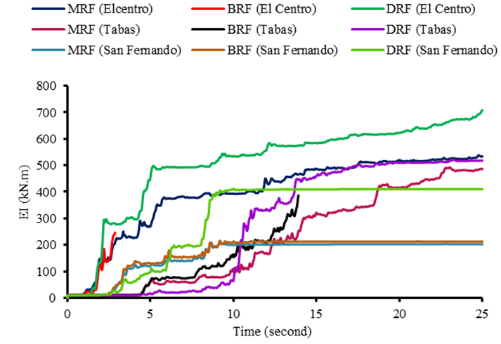 | Figure 16. Time history of input energy |
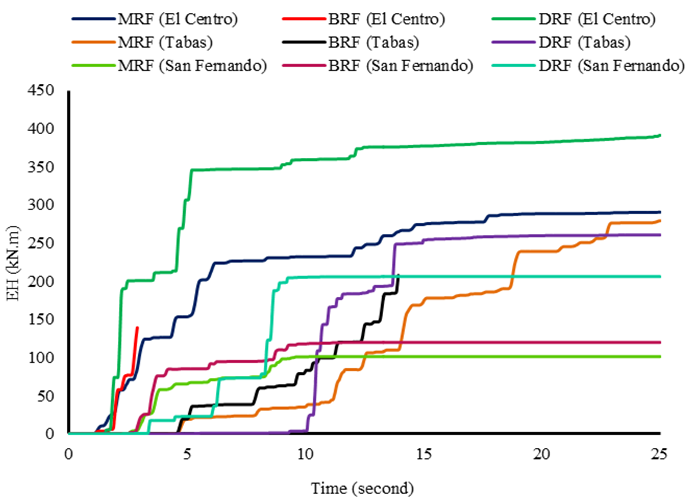 | Figure 17. Time history of hysteretic energy |
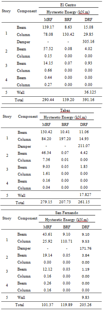
6.3. Distribution of Input and Hysteretic Energy Demand
- Many researcher believed that the damage to a structures depend on amount of hysteretic energy dissipated and on its cumulative effect. Figure 18 present the total hysteretic energy components, i.e., dissipated by beams element, columns element, walls and dampers element. For the MRF frame, energy dissipated by beams element larger than columns element. In contrast, most of input energy on the BRF frame absorbed by columns component rather than beams component. The absence of infill wall on the first story (discontinuous in the distribution of stiffness) exhibit the poor behavior on the lateral load carrying system of the structure. This is the reason why BRF frame indicate failure earlier than MRF frame during El-Centro and Tabas earthquake. In addition, for MRF frame in which the largest hysteretic energy demand caused by El-Centro ground motion followed by Tabas and San Fernando. Unlike MRF frame, for BRF frame the hysteretic energy demand under Tabas earthquake larger than El-Centro earthquake and the smallest hysteretic energy demand generated by San Fernando earthquake. Furthermore, DRF frame indicates good behaviour on the lateral load carrying system, although the input energy transmitted into this structure is much higher compare to other systems (MRF and BRF), particularly under El-Centro excitation. This behavior can be attributed to the concentrated a large portion of hysteretic energy demand on the damper devices, only a small portion of the input energy dissipated by main structural component such as: beams and columns. Therefore, building structure incorporated with hysteretic damper during strong earthquake excitation exhibit better performance, i.e. remain elastic or minor damage. Moreover, infill wall of the BRF frame does not play a role in the absorbing of the seismic input energy. On the contrary, infill walls element on the first story of the DRF frame have contributed to the energy dissipation. However, energy dissipated by this element are not significant compare to energy dissipated by damper device. Damper device are able to absorb more than 40% of the total input energy.
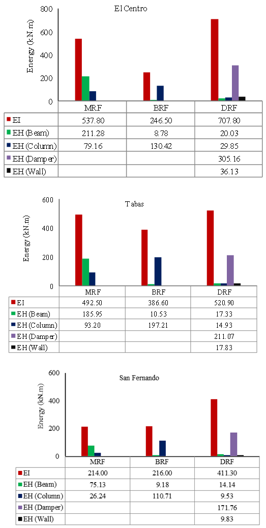 | Figure 18. Comparison of the hysteretic energy among the structural members |
|
6.4. Interpretation of Damage Level
- Damage level of the building under study can be predicted through response parameters such as: inter-story drift, plastic hinge rotation , cumulative hysteretic energy demand , damage index, and many others parameters. In this study damage index proposed by Park and Ang with
 to be used for predicting the damage level of the structures. Table 4 shows the comparison of the damage level of the structure using damage index and seismic performance based on inter-story drift under three selected earthquake scaled to 0.5g. It is clearly confirmed that MRF and BRF frames collapse due to El-Centro and Tabas earthquake. However, both frames only were extensively damaged under San Fernando earthquake. It was also demonstrated that DRF frame shows superior performance under strong seismic excitation, in which the worst condition of the structure indicates just moderate damage. Additional information was noticed that in this case there are correlation between degree of damage and inter-story drift. The higher inter-story drift, the higher the level of damage of the structures.
 7. Conclusions
- In this paper, the seismic performance of the r/c frame with and without considering the interaction of infill walls and structures is presented. By using steel damper incorporated into structure on the first story not only can avoid the structure collapse premature but also to improve the seismic performance of the structure having soft first story. Based on observation of the results obtained by nonlinear dynamic analysis, the following main conclusion can be drawn:• The presence of infill walls and absent at first story causes soft story mechanism, and lead to structural behavior more brittle. Building structure having soft first story exhibit a poor performance during strong seismic excitation. This condition will be aggravated if there is no infill walls on the first story while the above story stiffer due to presence of the infill wall.• Ground motion excitations scaled to the same PGA does not guarantee produce the similar response parameters of the building under consideration. Because the response of the building are not only influenced by building dynamic properties but also depend on ground motion characteristic, such as duration of motion, Frequency content and intensity parameter (PGA, PGV, others parameters).• Lateral deformation of the building structure with open space on the first story concentrated at the first story, while others story behave as rigid motion under strong earthquake. This building is prone to experience severe damage or collapse due to soft story mechanism.• By using steel damper incorporated into building structure on the first story can enhance the seismic performance of the building, and to prevent building collapse prematurely. The selection of stiffness ratio SR is important factor for successful in strengthening of building structure having soft first story.