-
Paper Information
- Next Paper
- Previous Paper
- Paper Submission
-
Journal Information
- About This Journal
- Editorial Board
- Current Issue
- Archive
- Author Guidelines
- Contact Us
Journal of Civil Engineering Research
p-ISSN: 2163-2316 e-ISSN: 2163-2340
2014; 4(3A): 149-153
doi:10.5923/c.jce.201402.26
Behaviour of Trapezoidal Roof Cladding under Different Location of Point Load
 Abstract
 Reference
 Full-Text PDF
 Full-text HTML
Majid T. A.1, Muhammad M. K. A.2, Noram I. Ramli1, Che Deraman S. N. A.1, Wan Chik F. A.1, Marcus N. G.1
1Graduate student, School of Civil Engineering, Universiti Sains Malaysia, Penang, Malaysia
2Coordinator, Disaster Research Nexus, School of Civil Engineering, Universiti Sains Malaysia, Penang, Malaysia
Correspondence to: Muhammad M. K. A., Coordinator, Disaster Research Nexus, School of Civil Engineering, Universiti Sains Malaysia, Penang, Malaysia.
| Email: |  |
Copyright © 2014 Scientific & Academic Publishing. All Rights Reserved.
The failures of roof claddings are very often caused by the uplifting force from the wind. The uplifting force normally will cause damage the support of the roof cladding which are attached to the purlins. When the roof cladding is subjected to wind uplift/ suction force, local dimpling or pull- through failure occur prematurely at their screw connections because of large stress concentration in the cladding at the vicinity of the screw heads. Currently, the design of roof cladding is mainly based on time consuming and expensive laboratory testing. In this study, a finite element model of trapezoidal was developed and validated with the experimental result to study the effect of point load to the trapezoidal roof sheeting. This paper presents the details of the finite element analysis using LUSAS.
Keywords: Uplifting force, Pull – through, Steel cladding, LUSAS
Cite this paper: Majid T. A., Muhammad M. K. A., Noram I. Ramli, Che Deraman S. N. A., Wan Chik F. A., Marcus N. G., Behaviour of Trapezoidal Roof Cladding under Different Location of Point Load, Journal of Civil Engineering Research, Vol. 4 No. 3A, 2014, pp. 149-153. doi: 10.5923/c.jce.201402.26.
Article Outline
1. Introduction
- Thin roof claddings are commonly made of thin and high strength steels widely used as roofing system for rural area in Malaysia. During high wind events such as thunderstorm, these cladding suffer from local pull through failure at fastener connection due to wind uplift loading. Loss of claddings always leads to a progressive collapse of the entire buildings. From the past research and field damage investigation shown that light gauge steel cladding may fail locally in the vicinity of screw fastener. Under the high wind uplift loading, the light gauge steel cladding often pull through the fastener head, in the presence of large stress concentration around the screw holes [1].Recently, there are many available commercial finite element analysis programs available in research. The used of finite element software can reduced time consuming and increasing the efficiency of the research. Finite element analysis (FEA) can be utilized to develop a numerical model of roof cladding subject to a variety of loads, proving the opportunity to study the response of roof cladding both efficiently and cost effectively. Previous studies developed the numerical models of roof cladding using FEA, have been successful in simulating the behaviour of cladding subject to static uplift pressure. The behaviour of cladding under static load was necessary for understanding the mechanism of local and global deformation. In order to simplify the model, both numerical models corrugated and trapezoidal cladding subject to static uplift pressure was often used in past study [2-4].
2. Development of Finite Element model
2.1. Structure Model
- The single span with single sheet model of trapezoidal roof cladding was analyzed using finite element program LUSAS Version 14. As a typical cases, a trapezoidal roof cladding system as shown in Figure 1 is considered in this paper. The span (L), depth (d), pitch (p) and thickness (t) of the cladding are 750 mm, 23mm, 190 mm and 0.3mm respectively.
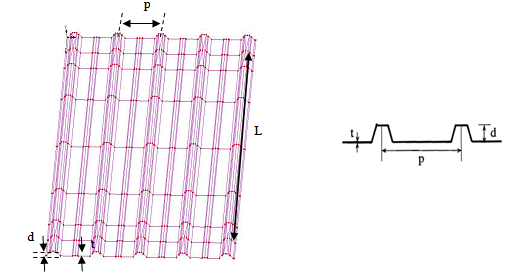 | Figure 1. Trapezoidal steel cladding |
2.2. Element and Meshing
- Two types of element were used. Four – node, quadrilateral thin shell elements (QSI4) with linear interpolation were used to model the trapezoidal steel cladding. Meanwhile, Three – node, triangle thin shell elements (TS3) with linear interpolation was used around the fastener hole. Selection of mesh size is a critical in the finite element modeling. As shown in Figure 2a, finer mesh was used around the fastener hole due to high local stress and deformation in the steel sheeting. To reduce the analysis time, course mesh was used to model pan and rip of the trapezoidal steel cladding. Figure 2b shows the course meshing used in the analysis.
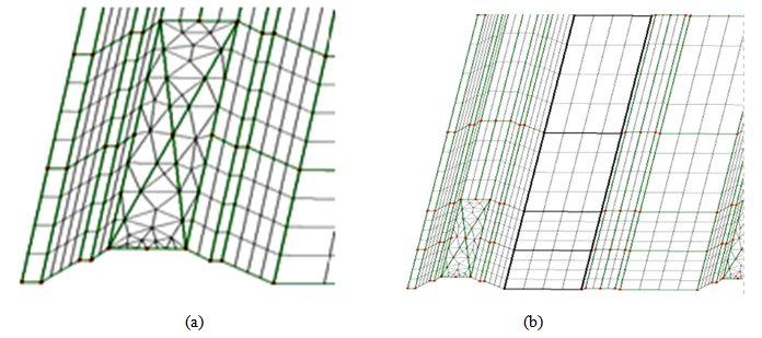 | Figure 2. Meshing used in the analysis a) fine mesh b) course mesh |
2.3. Material Properties
- The isotropic material properties of the trapezoidal roof cladding were included in the model. The material properties were obtained from the manufacturer. The following material properties of steel were used in the analysis: Modulus of elasticity E = 209 000 MPa and Poisson`s ratio assumed as 0.3.
2.4. Load and Boundary Condition
- Due to the symmetrical of the model, only upper quadrant of the model was consider in this study. Nine different location of point load was applied to the model to study the effect of location of point load. The static load applied to the model until failure occurred. The fastener constituted the boundary conditions of the model. To simplify the model, a fastener was assigned as pinned support at alternating crest which is fixed translation and free rotation in all direction. Figure 3 shows the location of point load applied to the trapezoidal steel cladding.
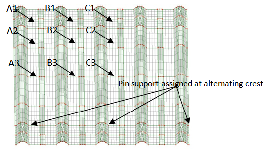 | Figure 3. Location of point load |
3. Validation of the Finite Element Model
- The FEA model`s performance was evaluated by comparing the response of the trapezoidal steel cladding with the corresponding experimental result. An inspection of deformation and deflection of the trapezoidal steel cladding. Experimental work has done with five different span which is 750mm, 850mm, 950mm, 1150mm, 1250mm under the similir loading sequence. However, the FEA used the 750mm span as the percentage difference shows a good argument between finite element method and experimental method All experimental testing method and apparatus used can be found elsewhere [5]. Figure 4 shows the comparison of experimental and FEA model result.
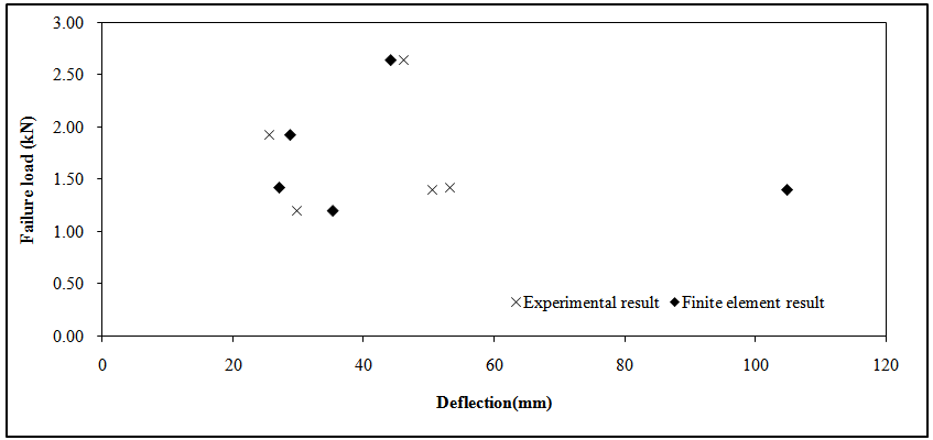 | Figure 4. Comparison of experimental and FEA result |
4. Result and Dissucsion
4.1. Point load on Unsupported Crest
- Point load on unsupported crest shows almost similar behaviour in all point 1B, 2B and 3B. The failure loads of all 3 point are almost similar, which is more than 2.0 kN. Failure for point 1B is 2.3kN, point 2B is 2.5kN and point 3B is 2.4kN. These values shows that at any point of the unsupported crest the failure load will vary around 2.0kN. Although the failure loads are almost similar, the deformation of the roof sheet may show different patterns. The stress versus load graph with combined lines of point 1B, 2B and 3B are relatively close to each other as shown in Figure 5. This shows that the behaviour for all three points is similar to each other with gradient of only slight difference. The failure load for the unsupported crest is much higher compare to the supported crest near the edge. This shows that loads acting on the unsupported crest does not induced a lot of stress compared to the supported crest at the edge.
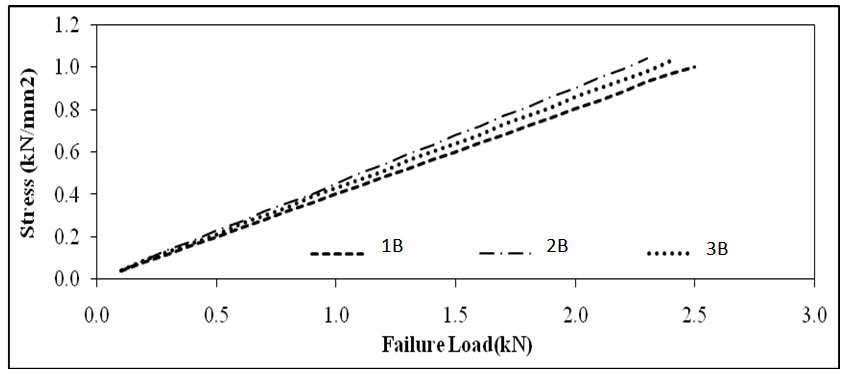 | Figure 5. Stress Versus load for point load locate at 1B, 2B and 3B |
4.2. Maximum Stress and Deform Mesh
- The stress contour for all three locations shows almost similar patterns. The stress area for unsupported crest is very large compared to the supported crest at the edge. From the contour as well it can be seen that the maximum stress are located at the support. This time failure occurs near the pin support area. The deformation of the model is very large as well as compared to deformation on supported crest. The large deformation explains the large area of stress around the model. The large deformation does not yield large stress although the stress area is quite wide. The large deformation can be explained by flexibility of the material with very small thickness therefore the stress is small. Figure 6 shows the stress contour and deformed mesh for location 1B, 2B and 3B respectively.
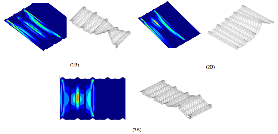 | Figure 6. Maximum stress contour and deformed mesh for location 1B, 2B and 3B |
4.3. Comparing All Failure Load
- Figure 7 shows the combination of all the results for the failure load at different location. It can be seen that the failure load ranges from 3.0kN to 0.8kN. Failure load at the centre crest of the model shows the most severe failure which is surrounding the support of the model. However, failure load at the other crests does not show any failure surrounding the support. Therefore, at the events of high wind speed it is best to avoid loading acting at the centre of the model which is the weakest point of the roof sheet. The behavior of the roof sheet can be estimated by how the roof sheet fails at different location of point load.
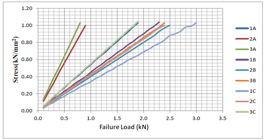 | Figure 7. Combination of result for all different location of point load |
5. Conclusions
- Finite element analysis can be used to develop numerical model to simulate the behavior of trapezoidal roof sheeting subject to point loading. The captured characteristic of the deformed shape of the finite element model of trapezoidal roof cladding were successfully simulate the deformed shape observed during experimental work. The used of finite element analysis would ultimately enable a cost effective and efficient means of studying the behavior and response of steel cladding subject to a variety loads.
ACKNOWLEDGEMENTS
- The author would like to express gratitude and thankful to Universiti Sains Malaysia for providing financial support from Delivering Excellence Grant for the research and Ministry of Education giving sponsorship under MyBrain15 throughout the studies.