-
Paper Information
- Next Paper
- Previous Paper
- Paper Submission
-
Journal Information
- About This Journal
- Editorial Board
- Current Issue
- Archive
- Author Guidelines
- Contact Us
Journal of Civil Engineering Research
p-ISSN: 2163-2316 e-ISSN: 2163-2340
2014; 4(2A): 26-30
doi:10.5923/c.jce.201401.06
FEA Studies on the Interfacial Behavior of Epoxy-CFRP Composites
 Abstract
 Reference
 Full-Text PDF
 Full-text HTML
S. Priya Dharsini1, B. Bhuvaneshwari2, G. S. Palani2, G. Mohan Ganesh2, Nagesh R. Iyer2
1Structural Engineering, VIT University, Vellore, 632014, India
2CSIR-Structural Engineering Research Centre, CSIR Road, Chennai, 600113, India
Correspondence to: S. Priya Dharsini, Structural Engineering, VIT University, Vellore, 632014, India.
| Email: |  |
Copyright © 2014 Scientific & Academic Publishing. All Rights Reserved.
Carbon fiber reinforced plastic (CFRP or CRP) is a light-weight and high strength composite material. Epoxy is the most commonly used as the associated bonding agent. CFRP is gaining more importance in the research field due to the emerging use in construction field mainly for strengthening of the structural elements as well as for repair and rehabilitation. Hence, detailed understanding on the interfacial behavior of the structural element- epoxy- CFRP is essential. The information available related to the interfacial behaviour of epoxy-CFRP is scarce. The CFRP- epoxy interface region is found to be the weakest region in the matrix. This study is focused on the bonding between the interfaces of epoxy- CFRP composites. A 2D micro-level Finite- Element (FE) model of transverse fibre bundle along with epoxy has been created by using the Finite Element Analysis (FEA) software, ABAQUS. FEA has been conducted to understand the interfacial behavior between the matrix and their effects on strength and stiffness. The effects of tensile and thermal stresses on the matrix are analyzed. The thermal stress is predominant at high temperature, which is compressive in nature.
Keywords: CFRP, FEA, Interface bonding, Epoxy
Cite this paper: S. Priya Dharsini, B. Bhuvaneshwari, G. S. Palani, G. Mohan Ganesh, Nagesh R. Iyer, FEA Studies on the Interfacial Behavior of Epoxy-CFRP Composites, Journal of Civil Engineering Research, Vol. 4 No. 2A, 2014, pp. 26-30. doi: 10.5923/c.jce.201401.06.
Article Outline
1. Introduction
- Micro-mechanical simulation is widely carried out to understand the interfacial behavior of CFRP/concrete. There are various problems when it comes to interface of CFRP/concrete. From the failures and the test concerned to CFRP, it is found that the major factors need to be considered are concrete delamination due to the moisture penetration and high temperature effect, fracture, stress concentration due to environmental factors, external loading etc., Hence, micro-mechanical simulation will give us a clear understanding of the interface when compared to mesoscale. They can also be used for verifying the test results. The von mises stresses and the stress patterns in the different axis of direction obtained from FEA will help us to predict the stress concentration. CFRP strengthening of the structural elements is an emerging topic in the field of repair and rehabilitation. The use of CFRP has increased rapidly in the present applications and researches. Some of the current FRP applications are low pressure pipes, diesel storage tanks, lube tanks, and utility tanks, walkway gratings, stair steps, and handrails, cable ladders and trays, fire protection panels and sections of accommodation modules, buoys and float, strengthening of primary steel structures, helicopter landing decks, walls and floors to provide protection against blast and fire. They are highly corrosion and heat resistant and increase the strength and durability of the structures. Their major application is the strengthening of the structures in which the interfacial behaviour plays an important role in the durability of the structure. Hence it has become essential to analyze the behavior of the CFRP- epoxy- structural element interactions to avoid the failure and delamination in the structural elements. Several studies were carried out on the bonding behavior of concrete/CFRP and CFRP/epoxy. Experimental investigations were carried out using different test methods like fibre bundle test, pull out test and microscopic analysis to analyze the debonding failure of the interface. The improved CFRP/epoxy bonding by incorporation of nanoparticles has also carried out by (Ying Zeng et al, 2012). FE micro analysis (Syam Prasadet al, 2013) and multi-scale modeling (Carlos Gonza´lez et al, 2006) was done on the interfacial properties, thermal properties, transverse tensile loading (Patrick Rosso et al, 2006). Mechanical behavior of concrete-CFRP was analyzed by using ABAQUS software based on various parameters such as number of layers of CFRP, column sizes, and mesh sizes in the literature (Pezhman Taghia et al, 2013).The failure of composites are often investigated by using computational micromechanics models, which offer the possibility of analysis and quantification of the failure mechanisms that take place at the micro-scale level. The response observed during the damage in the composites with high accuracy can be analyzed with the need for very few hypotheses. Though these kinds of analyses are common in current scientific literature, as far as the interfacial properties are concerned, the analysis performed are generally limited to the interface failure. Hence, the study finds enormous scope towards the interface failure analysis of CFRP/Epoxy/Concrete. It is difficult to analyze these problems by using the experimental method. Hence, modeling the CFRP-epoxy-structural element interface and analyzing with different parameters will give a better understanding. Many works are carried out on the FE modeling of the CFRP interface. But the micro mechanical modeling will give us the clear understanding on the interfacial behavior of the CFRP-epoxy-interface. A combined study of interfacial behavior of concrete- epoxy-CFRP on the micromechanical FE analysis is very scanty. In this present study a 2D FE micromechanical simulation is carried out to study the interfacial behavior. It is seen that the interface region is the weakest zone of the element which are the main cause for the initiation of the failure. In the previous studies (Denvidet al, 2012) it was presented that the moisture penetration in the interface layer causes the debonding in the element. High temperature change affects the interface and cause bond separation. Improper laying of the epoxy or CFRP layers, exposing CFRP in the moisture before interfacing with epoxy, improper bonding, chemical reactions are some of the reasons for the failure due to the interface. Hence study on the interfacial reactions plays an important role in preventing the onset of the failure, thus improving the quality of the CFRP strengthening.
1.1. Objective and Scope
- This study focuses on the bonding between the interfaces of Epoxy- CFRP. Micro-mechanical analysis is carried out which is essential to understand the failure criteria and the effect of the parameters which are the cause for the failure. The major parameters which affect the durability of structure such as tensile loading and temperature stress are analyzed by modeling and by simulation through FEA. ABAQUS software is used for FEA simulation. This paper aims at analyzing the behavior of the interface between CFRP-epoxy matrixes by the micro-mechanical simulation.
2. Materials and Methods
2.1. Modelling
- The 2D micro-level FE model has been created defining the material properties of concrete, epoxy and CFRP. The CFRP bundles were layered on the epoxy with the dimension of (135.5 X 200) µm and the concrete layer have been provided with the thickness of 100µm as shown in the Figure 2.1. The diameter of the fibre is taken as 7µm. The bonding between the fibre, matrix and the concrete is taken as perfectly bonded without the use of any interface elements. Four nodded linear quadrilateral elements (CPE4R) have been used. The total numbers of elements for the model are 374,297.
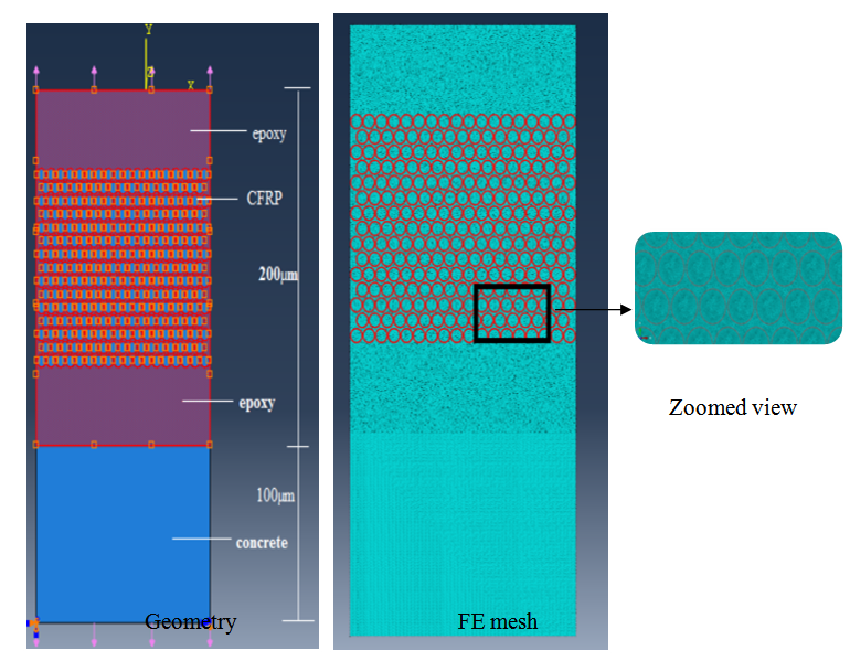 | Figure 2.1. Micro model of concrete-epoxy-CFRP |
2.2. Materials
- The properties of the materials used as the input data in the modeling are epoxy (Nanopox XP 22/0616, Hanse Chemie AG, Germany) mixed with a diglycidyl ether of bisphenol A (DGEBA) epoxy resin, Amine containing epoxy suspensions. T300 carbon fibres (FGI Fibre Glass International, Australia) with a nominal diameter of 7µm are used as fibre material. The properties of the material used are provided in the Table 2.1. The properties of the CFRP and the epoxy are taken from the literature (Jianing Zhang et al 2013). The concrete grade is taken as M20 and the concerned properties are used.The interfacial behavior of the Epoxy-CFRP is examined by the application of the unidirectional tensile load and temperature input. The bond between Concrete-Epoxy is assumed to be perfect in this model. The thermal stress and the loading are the main constraints, which form a change in the interface region. The interfacial region is the weakest zone in the composite, which gets easily affected by the application of the external stress or variation of temperature and other factors. In this study the model is tested with mainly two criteria for analysis as listed in the Table 2.2. The tensile loading is adopted based on the literature (Jianing Zhang et al 2013), where they conducted the fibre bundle test and the tensile load is obtained for the neat epoxy. The temperature variation is from 23℃ to 120℃ gives a mark able variation which helps in interpreting the interfacial behavior.
|
3. Results and Discussion
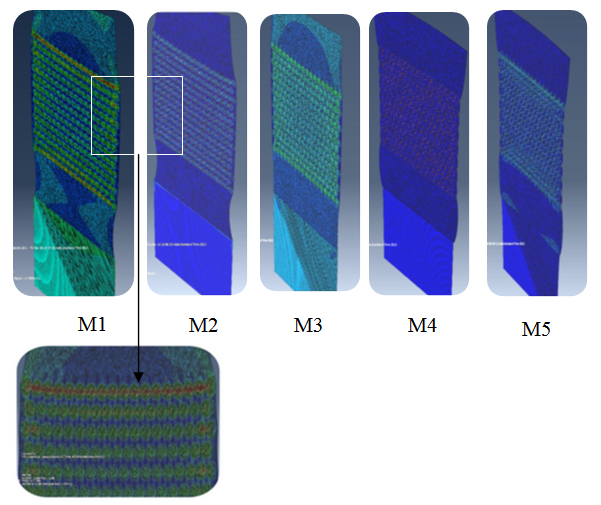
- The stress contour in Y direction in different conditions (M1 to M5) is shown in the Fig 3.1. By interpreting these stress patterns, it can be observed that when the temperature is increased to 120℃ the tensile stresses are getting suppressed by the compressive force created by the high temperature effect.
 | Figure 3.1. Stress in Y direction (S22) for all the conditions |
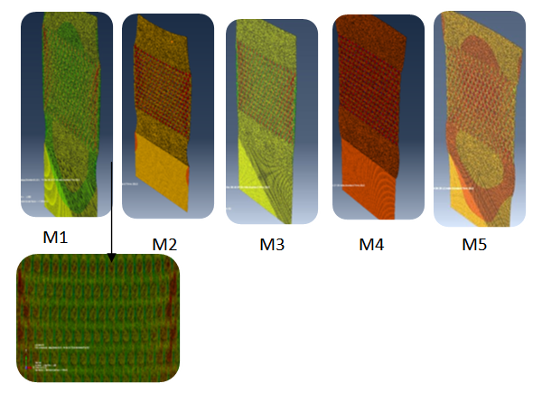
 | Figure 3.2. Von Mises stress (S) for all models |
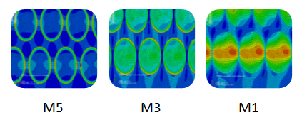 | Figure 3.3. Variation in Von Mises stresses |
|
4. Summary and Conclusions
- A combined study of interfacial behavior of Epoxy-CFRP on the micromechanical FE analysis is very scanty. In this present study a 2D FE micromechanical simulation is carried out to study the interfacial behavior. This study focuses on the bonding between the interfaces of Epoxy- CFRP. Micro-mechanical analysis is carried out which is essential to understand the failure criteria and the effect of the parameters which are the cause for the failure. The major parameters which affect the durability of structure such as tensile loading and temperature stress are analyzed by modeling and by simulation through FEA.When the tensile load alone is applied, the high stress is concentrated at top and the bottom fibres and some stress are extended to the concrete/epoxy interface. The tensile load predominates at the low temperature. At the elevated temperature, the temperature load generates high stress throughout, which is compressive in nature. When the tensile load is added to it, it has less impact as the temperature effect is predominant. The high stress extends to the sides of the concrete/epoxy region. The high stresses on the application of the tensile and temperature load does not occur on the same region. Thus the combined load application has overall effect in the CFRP/epoxy region. The effect of the tensile stress indicates that the top and bottom fibres are the location for the initiation of the damage.
ACKNOWLEDGEMENTS
- The paper is being published with the kind permission of The Director, CSIR-SERC, Chennai.
References
| [1] | Jianing Zhang, Shiqiang Deng, Yulong Wang, Lin Ye, Limin Zhou, Zhong Zhang., “Effect of nanoparticles on interfacial properties of carbon fibre–epoxy composites”, Composites: Part A 55 (2013) 35–44. |
| [2] | Patrick Rosso and Ka´roly Va´radi., “Fe macro/micro analysis of thermal residual stresses and failure behaviour under transverse tensile load of ve/cf – fibre bundle composites”, Composites Science and Technology 66 (2006) 3241–3253. |
| [3] | Carlos Gonza´lez, and Javier LLorca., “Multiscale modeling of fracture in fiber-reinforced composites”, Acta Materialia 54 (2006) 4171–4181. |
| [4] | K.-D. Bouzakis, I. Tsiafis, N. Michailidis, A. Tsouknidas., “Determination of epoxy resins’ mechanical properties by experimental-computational procedures in tension”, Surfaces and Materials Characterization 3rd ICMEN – 2008. |
| [5] | Denvid LAU., “Moisture-induced Debonding in Concrete-epoxy Interface”, The Hong Kong Institution of Engineers Transactions, Vol 19, No 3, pp33-38. |
| [6] | Syam Prasad. A, Syed Altaf Hussain, Pandurangadu. V., “Micromechanical analysis of frp composites”, International journal of mechanical engineering and technology, Volume 4, Issue 2, March - April (2013), pp. 272-285. |
| [7] | Pezhman Taghia and Suhaimi Abu Bakar., “Mechanical Behaviour of Confined Reinforced Concrete-CFRP Short Column- Based on Finite Element Analysis”, World Applied Sciences Journal 24 (7): 960-970, 2013. |
| [8] | Ying Zeng, Hong-Yuan Liu , Yiu-Wing Mai, Xu-Sheng Du., “Improving interlaminar fracture toughness of carbon fibre/epoxy laminates by incorporation of nano-particles”, Composites: Part B 43 (2012) 90–94. |