-
Paper Information
- Next Paper
- Previous Paper
- Paper Submission
-
Journal Information
- About This Journal
- Editorial Board
- Current Issue
- Archive
- Author Guidelines
- Contact Us
International Journal of Tumor Therapy
p-ISSN: 2163-2189 e-ISSN: 2163-2197
2015; 4(1A): 16-21
doi:10.5923/c.ijtt.201501.03
A Simplified Technique to Evaluate Risk Region Using Picture Editing Tools in Microsoft Word
Mohammed Ismael Abu Shariah1, Sawsan Kamel Shariah2
1Department of Civil Engineering-Mining & Mineral Resources Technology Canter, Northern Border University (NBU)
2Faculty of Creative Media and Innovative Technology, Infrastructure University Kuala Lumpur (IUKL)
Correspondence to: Mohammed Ismael Abu Shariah, Department of Civil Engineering-Mining & Mineral Resources Technology Canter, Northern Border University (NBU).
| Email: |  |
Copyright © 2015 Scientific & Academic Publishing. All Rights Reserved.
Microsoft Word allows some amazing image editing that can light creative simplified and fast technique to evaluate risk region by using picture editing tools to correct and improve images. Different images were applied, and satisfactory results were obtained of application objective in a smoothly way without losing any data of target object, only enhancing the image structure to delineate risk zone and its features.
Keywords: Microsoft Word, Picture Editing Tools, Risk Region, Fractures, Seismic Reflection
Cite this paper: Mohammed Ismael Abu Shariah, Sawsan Kamel Shariah, A Simplified Technique to Evaluate Risk Region Using Picture Editing Tools in Microsoft Word, International Journal of Tumor Therapy, Vol. 4 No. 1A, 2015, pp. 16-21. doi: 10.5923/c.ijtt.201501.03.
Article Outline
1. Introduction
- Digital image processing is a rapidly evolving field with applications to many areas of technology and science. Image processing techniques include restoration of image distortions, reconstruction of images from indirectly sampled data. These image-processing techniques have many applications in remote sensing, geophysics, medical, civil engineering, astronomy and space research, radar and sonar imaging [1]. The recent rapid advances in medical imaging and automated image analysis will continue and allow us to make sign cant advances in our understanding of life and disease processes, and our ability to deliver quality healthcare [2]. Medical imaging and image processing used through several researches such as segmentation of Microscopic Bone [3], An Enhance Fracture Detection Algorithm Design Using X-Rays Image Processing [4], An Enhanced Tibia Fracture Detection Tool Using Image Pro-cessing and Classification Fusion Techniques in X-Ray Images [5], and others [2, 6, 7]. Traditional methods for rock mass characterization in civil engineering applications include scanline surveying, cell mapping and geologic structure mapping. In spite of their importance, characterizing rock masses using these field methods is time-consuming, hazardous and prone to errors [8] such as Image processing used for safety assessment in Civil Engineering [9], for studying Geological and Geomorphological Features [10], for studying mineral deposits [11], for studying cracks and fractures [12, 13 ].Microsoft Word (MS Word) has the ability to enhance images by adding effects, such as shadows, glows, reflections, soft edges, bevels, and three-dimensional (3-D) rotations to it. It can also add an artistic effect to a picture or change the brightness, contrast, or blurriness of a picture through picture editing tools [14]. In this study, Picture editing tools used to enhance several images to provide supplementary results that are useful for assessing fractures zone and evaluating risk region. Picture tools enhances an images of a CDP (Common depth midpoint) seismic reflection sections to provide supplementary results that are useful for assessing geohazard zones; the results in the images purify clearly the exact location and geometry of cavities and sinkholes, beside localization the areas that are under stress, and delineate the risk zones. In additional, this technique applied in fracture analysis and medical applications. Results were satisfactory in a smoothly way without losing any data of target object, only enhancing the image structure to obtain research paper's objectives.
2. Picture Editing Tools in Microsoft Word
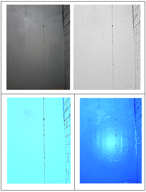
- In Microsoft Office 2003 or earlier, when dealing with an image a Picture Toolbar is made available when you are working with an image [15]. After inserting an image the toolbar may be displayed automatically. If it is not, right click the image and select Show Picture Toolbar [15] as shown in Figure 1.
 | Figure 1. Example of picture tools in MS Word |
2.1. Apply an Artistic Effect to a Picture
- The command located in the ‘Adjust’ group provides 23 special effects, such as pencil sketch, blurring, charcoal sketch, paint strokes, and others making picture appear to have been made from various mediums [16].
2.2. Image Corrections and Colour Settings
- This tool has the ability to adjust the relative lightness of a picture (brightness), the difference between the darkest and lightest areas of a picture (contrast), and the blurriness of the picture. These are also referred to as colour corrections [17].This tool has the capability to bring out detail in over or under-exposed pictures by brightening the picture or change the definition of the borders between light and dark by increasing or decreasing contrast. To enhance photo details, sharpen the picture, or to remove unwanted marks on the picture and soften it [17].
2.3. Other Functions
- Other functions in picture tools are background remover, 3-D options, compress pictures…etc. Compress Pictures Compress pictures; users can manually resize images or pictures in the Word document using Compress feature. When you press the option a dialog box appears displaying the following Compression options [18]:1. Apply only to this picture: Select whether you want to compress or modify selected pictures or all the pictures in document.2. Delete cropped areas of pictures: Removes the areas of images that you have cropped out. Cropped areas once removed cannot be retrieved.
3. Application Picture Editing Tools of MS Word
- Picture Tools” applied to Seismic reflection, fracture analysis, and medical applications as following;
3.1. Application Picture Editing Tools in Seismic Reflection
- The significance of CDP seismic reflection section emerges considerable in detecting the geohazard of buried karstic limestone as bedrock in developed area as shown in Figure (2). Therefore, the seismic reflection using CDP techniques is applied to verify the following objectives, which are to determine the depth of the bedrock and thickness of the soil, and to give the best image about the subsurface conditions and karstic features.CDM seismic reflection section is shown in Figure (2). It shows the displacement systems in the limestone bedrock. These displacements are associated with the development of sinkholes and slow subsidence in this region, which are caused by chemical dissolution. The first strong reflector from the limestone is located at 40 ms in two way time. The low amplitude reflector zone is illustrated in the middle of CDP seismic section. This anomaly corresponds to the fracture zone or sinkhole, which is located in the area. The CDM seismic reflection section in Figure (2), shows the poor reflector data quality. These anomalies are related to possible cavity system within the limestone bedrock [19-22]
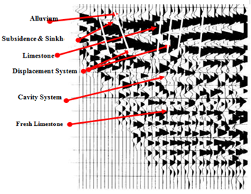 | Figure 2. Original image of CDP seismic reflection section [19, 20] |
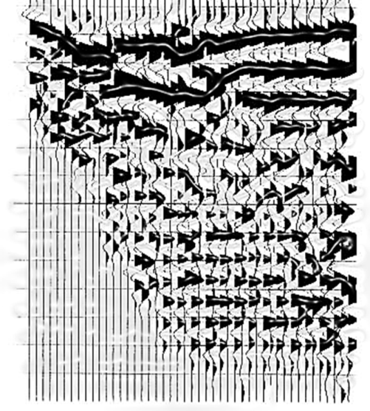 | Figure 3. Image of CDP seismic reflection section enhanced based on Picture Tools |
3.2. Application Picture Editing Tools to Delineate and Analysis Fractures
- Construction cracks are representing the best way to know a fault in a construction that needs to evaluate and diagnose them, to study reasons, and determine renovation and reparation techniques. Commonly, most cracks occur due to tensile stress induced by shrinkage or stress based on several reasons and their types.Figure (4) shows an image of granite rock building is filtered based on picture editing tools by using artistic effect (photocopy) and image corrections functions based on increase the sharpness and brightness as shown in Figure (4). This technique is preliminary focus on the weakness systems. It delineates the diagonal and vertical cracks with high accuracy and low-cost method as shown in Figure (4).
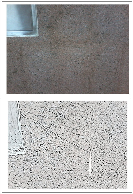 | Figure 4. Image of granite rock building is filtered based on picture editing tools by using artistic effect (photocopy) and image corrections functions |
3.3. Application Picture Editing Tools in Medical
- A bone fracture (sometimes abbreviated FRX or Fx, Fx, or #) is a medical condition in which there is a break in the continuity of the bone. A bone fracture can be the result of high force impact or stress, or a minimal trauma injury as a result of certain medical conditions that weaken the bones, such as osteoporosis, bone cancer, or osteogenesis imperfecta, where the fracture is then properly termed a pathologic fracture [24]."Most often, lateral ankle sprains are caused by an "inversion" injury of the ankle (Figure 6). In these injuries a strong force pushes the foot inward underneath the leg. The foot then buckles inward, towards the opposite foot. An example of this mechanism is when an individual comes down from a jump and lands with the ankle turned inward. As the weight of the body further loads the ankle, the foot buckles inward and the lateral ligaments of the outer ankle are torn" [25]. Figure (6) shows an image of broken fibula bone is filtered based on picture editing tools by using artistic effect (glow edges) and image corrections functions based on decreases the brightness and increase the contrast as shown in Figure (6). This technique is earliest focus on the broken fibula bone location. It has the ability to delineate the broken bone location with acceptable accuracy and low-cost method as shown in Figure (6).
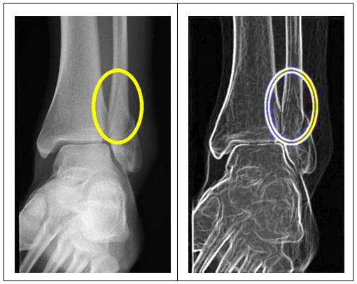 | Figure 6. Image shows broken fibula bone [25]. The left image after enhancing based on Picture Tools |
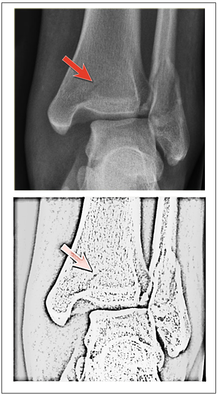 | Figure 7. Image shows linear lucency indicating a fracture of the malleolus tertius [26] and picture tools used to enhance and delineate fracture clearly |
4. Conclusions
- Picture editing tools - MS word used to create simplified and fast technique to evaluate risk region by correcting and improving images with acceptable accuracy and low-cost. Results were satisfactory in a smoothly way without loosing any object data, only enhancing the image structure to enhance the object and delineate risk zone Cleary in different application such as seismic reflection section, karstic limestone features, fractures analysis, medical examples. Therefore, this technique was amazing as initial and simple technique to obtain the research paper's objective successfully. It is recommended to use in several fields such unobvious object such as narrow fissures, hairline cracks and stress fractures.
ACKNOWLEDGEMENTS
- The authors wishes to acknowledge all their appreciation to their children (Yasmin, Al-Leith, Al-Reem, Al-Leen, and Al-Geith), and their community members in Northern Border University (NBU) and Infrastructure University Kuala Lumpur (IUKL).
 Abstract
 Reference
 Full-Text PDF
 Full-text HTML