-
Paper Information
- Previous Paper
- Paper Submission
-
Journal Information
- About This Journal
- Editorial Board
- Current Issue
- Archive
- Author Guidelines
- Contact Us
Energy and Power
p-ISSN: 2163-159X e-ISSN: 2163-1603
2016; 6(1A): 33-35
doi:10.5923/c.ep.201601.06

Compressed Air Engine with Self Compression Arrangement System
 Abstract
 Reference
 Full-Text PDF
 Full-text HTML
G. Sujaykumar, Sushiledra R. M., Varun Nayak
Department of Mechanical Engineering, Yenepoya Institute of Technology, Moodabidri, India
Correspondence to: G. Sujaykumar, Department of Mechanical Engineering, Yenepoya Institute of Technology, Moodabidri, India.
| Email: |  |
Copyright © 2016 Scientific & Academic Publishing. All Rights Reserved.
This work is licensed under the Creative Commons Attribution International License (CC BY).
http://creativecommons.org/licenses/by/4.0/

An Air Driven Engine makes use of compressed air technology for its operation. If we compress normal air into a cylinder the air would hold some energy within it. When this compressed air expands, the energy is released to do work. So this energy in compressed air can also be utilized to displace a piston. For this work several modifications have to be done on the engine to suit our purpose. The modifications comprised of following: Closing the transfer port, closing the inlet port, removing the spark plug from the cylinder head and providing an inlet at the place of the spark plug. Air powered engines are available with filled compressed air storage tank which will be filled by compressor unit. Pressure inside the compressed air tank decreases because of continues injection of compressed air into the cylinder. Reciprocating compressor was employed to maintain constant pressure in the compressed air storage tank. The pneumatic engine of small dimensions, however with high power fulfill the regulations of the environmental protection with zero emission which will reduce the global environmental problems.
Keywords: Compressed air engine, Two stroke engine, Solenoid valve, Chain drive, Self compression arrangement
Cite this paper: G. Sujaykumar, Sushiledra R. M., Varun Nayak, Compressed Air Engine with Self Compression Arrangement System, Energy and Power, Vol. 6 No. 1A, 2016, pp. 33-35. doi: 10.5923/c.ep.201601.06.
Article Outline
1. Introduction
- Since last few decades, energy crisis and carbon emission have become very concerning issue. Researchers are working on finding new ways to reduce dependency on conventional fuels and reducing carbon emissions. Researcher are finding new methods that use green energy viz. electric engines, hydrogen engines, and natural gas engines etc. Hydrogen engines can be used in the motor vehicles; however, storage and handling is concerning issue for hydrogen as fuel. Electric engines/ motors have been developed and commercially used since decades. However; slow battery recharging and high weigh weight batteries critical issues. Natural gas engine has a lot of potentials to be used in motor vehicles Air Driven Engine makes use of Compressed Air Technology for its operation. Compressed Air Technology is now widely preferred for research by different industries for developing different drives for different purposes. This is the basic working principle of the Air Driven Engine. It uses the expansion of compressed air to drive the pistons of the engine. So an Air Driven Engine is basically a pneumatic actuator that creates useful work by expanding compressed air. This work provided by the air is utilized to supply power to the crankshaft of the engine. There are several technical benefits of using air engines. For example no combustion takes place inside the cylinder. This helps reduce friction, wear, and tear of the engine components. This helps the engine run smoother than regular combustion engines. With air engines there is also no need for the installation of cooling systems or a fuel injection system. This makes the design simpler. In the air engine air is compressed using a compressor which uses electricity to run. It can be used in automobile industries as well as power generation. This adds value to its economic benefits. Also, the air engine will require less maintenance. In research studies it showed that the exhaust temperature of this engine should be less than the atmospheric temperature because there is no combustion in the cylinder and only air expanded to low pressure. It is non-polluting and less dangerous. It requires lighter metal only since it does not have to withstand elevated temperatures. So this will help in cooling the environment and if this technology is widely used than it could possibly help control global warming. When running the exhaust emissions will be air. This eliminates the problem of harmful emissions, in today’s regular engines. This gives us an environmental benefit of using this engine. Also the components used in this are a conventional engine, air. By having affordable components it makes the technology easily adaptable.In the experiment the independent variable will be the engine psi. The dependent variable would be the efficiency of the compressed air engine. In this project different air pressures will be tested to see its effect of the torque of the engine. Depending on the air pressure it will either increase or decrease the torque of the engine.The main theory of my experiment is that a higher air pressure will result in the highest energy output as there is no heat loss from the cylinder. This is understood through the basic knowledge of physics. A lower air pressure would probably give a low energy output as it exerts low pressure on the piston.
2. Experimental Details
- A single cylinder air cooled 2-Stroke engine was used with some modification as air engine.
|
2.1. Modification of 2 Stroke Engine
- Two stroke engines emit more pollutants than the four stroke engine. Two stroke engines can be used as compressed air engines with few simple changes. To covert four stroke engine in to compressed air engine, cam design is required.
2.1.1. Closing the Inlet and Transfer port
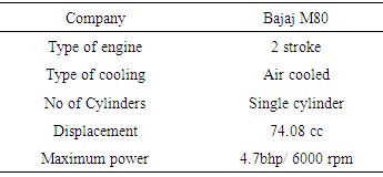
- The transfer port and inlet port should be closed to provide maximum sealing of the piston- cylinder arrangement so that the chances of escape of air from the cylinder can be avoided. We made plate and with nut and bolt connection transfer and inlet ports are closed.
 | Figure 1. Closing of inlet and transport port |
2.1.2. Removing the Spark Plug and Providing an Inlet at the Same Place
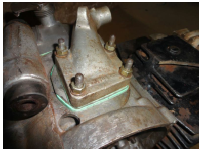
- As the petrol is not the fuel for the engine so no combustion process inside the engine cylinder therefore the spark plug is removed from the cylinder and an inlet is provided in that place by the help of connector. The connector is made by the lathe work and it has 10mm inner diameter as shown in Figure 2.
 | Figure 2. Modification of port |
2.1.3. Engine Shaft Modification
- Engine is powered by the compressed air not by the petrol and spark plug is eliminated therefore magnet is removed for the extension of shaft. After removing the magnet the connector which was already existed in the magnet assembly is used to extend the engine shaft. Engine shaft fixed by Allen key and bolt connection. Shaft is extended up to 190mm to attach test rig to find out break power and to align chain sprocket for self-compression system attachment. The extend shaft is consist of a valve timing disk plate, one pulley for rope brake dynamometer and a sprocket for self-compression system and a bearing for the support.
2.1.4. Other Modifications
- Solenoid valve with valve timing disc is used. Both are connected to an electric circuit which receives the signal from the disc and controls the opening and closing of inlet to cylinder through the solenoid valve depending on crank angle. Relay switch is arranged near the rotating disc. When magnet fixed on the disc at particular angle passes in front of relay switch, it will close the circuit, which sends the signal to solenoid valve to open. Solenoid valve allow the compressed air through it.
2.1.5. Engine Working after Modification
- After closing the inlet and transfer port the engine with inlet at the place of spark plug and there is no change in the exhaust port. Mixing of air and fuel through a carburetor is eliminated because only air is the working medium. Only working and exhaust stroke exist with this modified engine. The modified engine now has only inlet and exhaust port with working and exhaust stroke. In petrol engine the cycles start with suction of petrol and air fuel mixture but here there is no suction stroke. Compressed air is injected through a connector when the piston at the TDC of the cylinder. The piston moves downwards or to the BDC because of sudden expansion and distribution of pressurized air on the piston head and this is the working stroke of the modified engine. When piston moves downwards the air injection will be stopped and this completes the half rotation of the crank shaft and piston comes from BDC to TDC due to the inertia force. At this time air will move out through the exhaust port due to piston movement and this is the exhaust stroke of the engine.
3. Results and Discussions
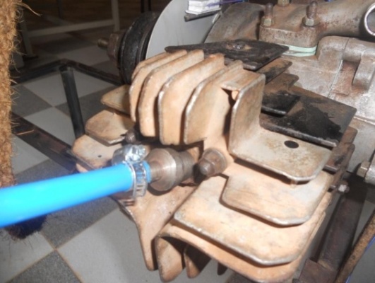
- Performance analysis is carried out for both with self air compression and without self air compression system.Figure 3 shows that Brake power is increasing with increase in pressure and Break power without compression system is more than that of with compression system.
 | Figure 3. Brake power Vs Pressure plot |
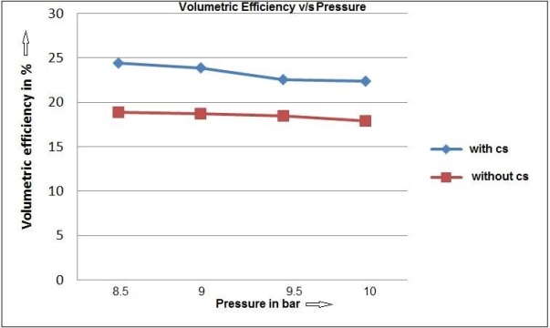 | Figure 4. Volumetric efficiency Vs. Pressure |
4. Conclusions
- There is a necessity to move towards alternate fuels because of depleting fossil fuels in nature. Compressed air can be used as an alternate fuel which is eco-friendly. Compare to fossil fuels compressed air is cheaper and easily producible. Most importantly we can use the existing engine as air driven engine by making small modifications. The main cylinder pressure can be maintained by using self-compression system which is driven by part of the output power of the engine. As inlet pressure increases the brake power of the engine also increases. Only 20% brake power of the engine utilized by the self-compression system with the pressure ranging from 8.5-10 bar. To achieve the speed required for the compressor from the engine to develop pressures of 2-10 bar the sprockets should be designed.