Dheeraj N. A., Nishanth, Sharath Rao, Royal Steevan Vas, Rathnakar M.
Department of Mechanical Engineering, St Joseph engineering College, Mangaluru, India
Correspondence to: Dheeraj N. A., Department of Mechanical Engineering, St Joseph engineering College, Mangaluru, India.
| Email: |  |
Copyright © 2016 Scientific & Academic Publishing. All Rights Reserved.
This work is licensed under the Creative Commons Attribution International License (CC BY).
http://creativecommons.org/licenses/by/4.0/

Abstract
A Polymer Electrolyte Membrane (PEM) fuel cell uses the chemical energy of hydrogen to cleanly and efficiently produce electricity. If hydrogen is the fuel, electricity, water, and heat are the only products. Also, fuel cells are quiet during operation as they have fewer moving parts. For the better performance of the fuel cell stack, uniform distribution of reactants, minimum pressure drop and flow losses are desired. Uneven distribution of reactants from the manifold to cells will lead to the poor performance of the fuel cell. Thus it is very much essential to give importance to the inlet geometry of fuel cell stack manifold. In this paper, 5-pass serpentine channel fuel cell stack consisting of 20 cells and 50 cells has been considered for modelling of three geometries for the inlet manifold namely rectangular, short diffuser and long diffuser. The proposed model is governed by mass and momentum conservation equations. Suitable convergence criteria for mass and momentum calculation were set. Velocity boundary condition for the inlet of the manifold has been calculated by using suitable formula. The model is numerically implemented using commercial CFD tool ANSYS-FLUENT 12.1. Flow and pressure distribution for the manifold and channel regions with three different inlet geometries have been simulated and analysed thereafter to reveal the influence of manifold inlet geometry on the flow distribution in the manifold and the channels.
Keywords:
Fuel cells, Manifold, Computational Fluid Dynamics, Serpentine flow channels, Bipolar plates
Cite this paper: Dheeraj N. A., Nishanth, Sharath Rao, Royal Steevan Vas, Rathnakar M., Fuel Cell Stack Manifold Optimization through Modelling and Simulation, Energy and Power, Vol. 6 No. 1A, 2016, pp. 15-21. doi: 10.5923/c.ep.201601.03.
1. Introduction
Energy needs in the world continue to increase due to increase of population and the economic growth, driving demand at an unsustainable pace. Oil will not suddenly run out, but it is a finite resource. We must develop energy efficient technologies and renewable energy technologies that can stretch fossil fuel reserves while we modify our energy-use patterns and infrastructure to become more sustainable over the next few decades. A sustainable energy portfolio should include a variety of carbon-neutral technologies.A fuel cell is a device that converts the chemical energy of the fuel into electricity through a chemical reaction of positively charged hydrogen ions with oxygen or another oxidizing agent. They convert hydrogen, or hydrogen-containing fuels, directly into electrical energy plus heat through the electrochemical reaction of hydrogen and oxygen into water. The process is that of electrolysis in reverse.Overall reaction: Flow mal-distribution in the channels of a single cell PEMFC has been addressed by numerical simulations and experimental studies. At the stack-manifold level, due to the complexity of structure and the lack of experimental techniques to measure the instantaneous flow distribution, not much work have been done in this direction. Thus, the present work focuses on the effect of manifold flow mal-distribution at stack level. Hong Liu et al. [1] has concluded that the serpentine channel is the best design among the 7 types of flow channels as the power obtained from it is maximum, they observed that multipass serpentine channel is best compared to single serpentine channel. Vijay Edupuganti and Bevin Daglen [2] found numerically that the pressure drop decreased with increasing channel to land ratio for both the serpentine and parallel channels. They also found that the parallel channels have comparatively less pressure drop as compared to the serpentine channels. The lower the pressure drop in the channels, the lower the losses due to friction, and the better the mass flow rate of the reactants to the GDL layer. Centre of the parallel channel design had less pressure resulting in uneven distribution of reactants along the GDL interface. In serpentine design the fluid was distributed more uniformly than parallel design. Jesper Lebaek [3] found that the circular type inlet had more uneven distribution of reactants among the cells as compared to the diffuser type inlet. They concluded that the inlet geometry of the manifold seems to have a large influence on the flow distribution. S. Pandiyan et al. [4] designed and analysed the performances of PEMFC. They concluded that the pressure variation is influenced by manifold size and geometry. Their results shows that the manifold to cell flow mal-distribution can critically affect the performance of the fuel cell stack, and this mal-distribution can be reduced by increasing the manifold dimension area. Chung- Hsien Chena et al. [5] studied the flow distribution in the manifold of PEMFC stack. In this study, manifold pressure variation and flow distribution of a fuel cell stack are simulated by CFD. This study explains different air feed will cause different flow distribution. Lesser air feed causes more uniform distribution than higher air feed. Channel design with large flow resistance is advantageous for flow distribution. While manifold widths increase, a more uniform flow distribution will be achieved. For manifold design in stacks, its width should be enhanced as much as possible and this is also beneficial for lowering overall stack pressure drop. R. Govindarasu et al. [6] has made an attempt made to experimentally investigate effect of channel geometry on PEMFC performance with different number of cells at various load and no load conditions. The experimental results clearly indicate pressure drop variation between first and last cells increases with the number of cells and stoichiometric ratio of reactants. B. Sreenivasulu et al. [7] studied the effect of back pressure and flow geometry on PEMFC. The performance of the fuel cell increases with an increase in back pressure in the flow channels due to an increase in residence time of hydrogen in the channel. As a result there is an increase in the diffusion rate of hydrogen across the gas diffusion layer. The 4-Serpentine flow channel helps in obtaining the highest power output both without and with back pressure. At higher back pressures the dual inlet and single outlet flow channel performs better than the interdigitated channel. Junye Wang [8] studied flow distribution and pressure drop in different layout configurations with Z-type arrangement. The results revealed pressure drop in the single serpentine may be as a hundred times as those in the straight parallel configurations. The study by Jaewan Park and Xianguo Li [9] showed that the effect of flow distribution on the stack performance is found to be considerably less for the Z configuration. Jinshi Wang [14] studied the flow mal distribution in channels of PEMFC stacks. For the design parameters, the arrangements listed below can reduce the flow maldistribution: lower area ratio of channel to port (including larger manifold size/cross-sectional area (widths)); lower flow channel sizes; lower manifold resistances; lower number of channels; lower number of gas flow channels per bipolar plate; larger channels flow resistance (varied by changing the permeability of porous media) and larger flow channel lengths. For operation conditions, lower feed gas rate/ velocity and using the H2/O2 reactants can improve the flow distribution and get a better fuel cell stack performance. There is no linear relationship between stoichiometry rates and relative humidity and the flow distribution. Hong Liu et al. [12] studied on flow distribution uniformity in fuel distributors having multiple structural bifurcations of flow channels. This work studied the issue of uniform flow distribution for general applications in fuel cells and fuel processing reactors, as uniform flow distribution is frequently advantageous in providing better heat transfer, temperature control, and low pressure loss, which is translated into less pumping power, as well as minimization of flow-related vibrations, noise, stresses, and corrosions due to bad flow uniformity. The effect of the curvature of channels at the 90° turning area was also studied and round corners were found to be very beneficial to the flow distribution uniformity at relatively low pressure loss.
2. Model Description
Pure hydrogen and air are considered as the reactant in the model. The gases enter manifolds through inlet ports, and then are distributed into each cell by manifolds and reach the electrodes through diffusion across the dilated membrane. After the electrochemical reactions are completed, un-reacted gases and products are discharged into manifolds from cells and then leave stacks through outlet ports. This flow field networks constitute an overall gas transport path. The modelled design was only cathode where air is used as an oxidant. The inlet flow velocity was controlled by stoichiometry of 1.2 at the anode and 2.0 at the cathode. The operating pressure was 0 kPa absolute at the exit of the cell. Suitable calculations were made to find out the inlet velocity of air depending upon the power and the current density. In the modelling of the fuel cell the following assumptions were made:- The cell operates under steady-state conditions.- The flow in the manifold regime is considered to be turbulent.- The fuel cell serpentine channels have laminar flow due to the micro channels. - Reactant and products are assumed to be ideal gas mixtures.- Air is the working fluid;- Electrochemistry, heat and mass transport phenomena are ignored.- Negligible gravity effect.
2.1. Numerical Modelling
The gas channels in a single cell have been modelled keeping in the practical dimensions of fuel cell into account. The PEMFC model is governed by the equations of conservation of mass and momentum.
2.1.1. Conservation of Mass
In fluid dynamics, the continuity equation states that, in any steady state process, the rate at which mass enters a system is equal to the rate at which mass leaves the system.Rate of increase in fluid element = Net rate of flow of mass into fluid element.The differential form of the equation is: | (1) |
2.1.2. Conservation of Momentum
Newton’s second law states that the rate of change of momentum of a fluid particle equals the sum of forces on the particle. This has been formulated into momentum equation.Rate of increase of momentum of fluid particle = Sum of forces on fluid particle.The differential form of the equation is: | (2) |
Where  denotes the partial derivative in the 3 dimensions,
  is the density of the fluid,
  is the velocity of fluid,
  signifies the pressure component in three dimensions,
  signifies the viscosity component in three dimensions.
2.2. Mesh Configurations
2.2.1. Channel Geometry
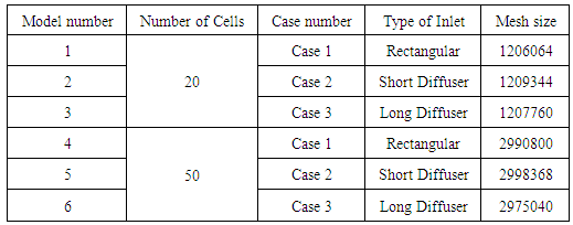
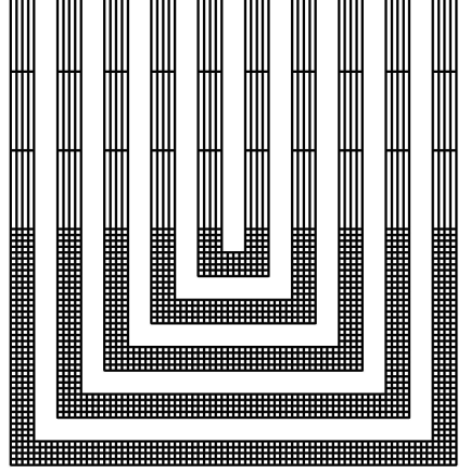
Bipolar plates are used to supply reactants, and to remove excess product from PEM fuel cells. Proper flow field designs will increase the evenness of reactant supply as well as increasing the water removal rate, which can lead to substantially improved performance. There are, however, four conventional designs which are used frequently in industry, and therefore viable for comparison. These four designs are as follows: pin, parallel, serpentine, and interdigitated. Each of these designs has its own unique set of benefits and detriments. The pin type designs have the most uniform reactant distribution, as well as very low pressure drop, but have very poor water management capabilities and low flow velocity. Parallel type designs also have very low pressure drop, but still have water management issues that tend to cause channel blockage. Serpentine designs tend to have better water management capabilities and flow velocity when compared with pin and parallel type designs, but at the cost of much longer flow paths, which result in uneven reactant distribution and higher pressure drop. Interdigitated designs force flow through the gas diffusion layer (GDL), which greatly improves their water removal capabilities without increasing the length of the flow paths, but results in the highest pressure drop of any of the four designs, which leads to increased parasitic power losses. Hence we consider serpentine design because of their generally higher power output and increased water management capabilities. The active manifold area was selected to be 7cm*7cm. Micro channels of 1mm*1mm were considered since the flow of fluid in the serpentine channels is being assumed laminar.Table 1. Model cases
 |
| |
|
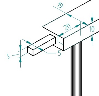 | Figure 1. Rectangular Inlet |
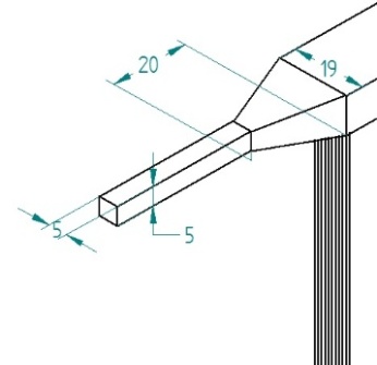 | Figure 2. Short Diffuser Inlet |
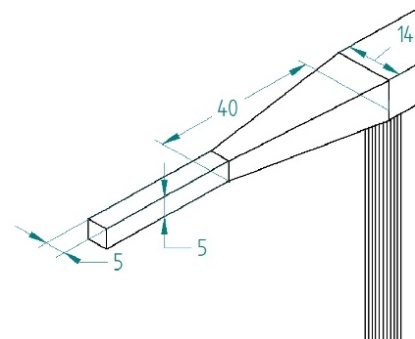 | Figure 3. Long Diffuser Inlet |
3. Numerical Implementation
3.1. Modelling
The finite volume method and implicit solver have been applied to solve the governing equations and the appropriate boundary conditions. The models were simulated using the CFD software ANSYS Fluent® 12.1 with Gambit® (2.4.6) as a pre-processor. The meshes were more refined at the bend regions in each of the single cell. The conservation of mass, momentum equations in the three-dimensions were solved, in turn, until the iterative process met the convergence criteria. In this study, the definition of convergence criteria indicates that the largest relative error between two consecutive iterative residuals within the overall computational domains is less that 10-6. The domain was divided into hexahedral volume elements. The model was based on the standard k-ε model which considered two separate equations for turbulent kinetic energy and it’s rate of dissipation. The solution strategy was based on the SIMPLE algorithm, while first order upwind methods were used to solve other terms. The under relaxation factors were taken default. Momentum equations were solved for the velocity, followed by solving the equation of continuity, which updates the pressure and the flow rate. Results were then verified for convergence of 10-6. Also the simulations were validated for mass flux at both inlet and outlet faces to check for errors.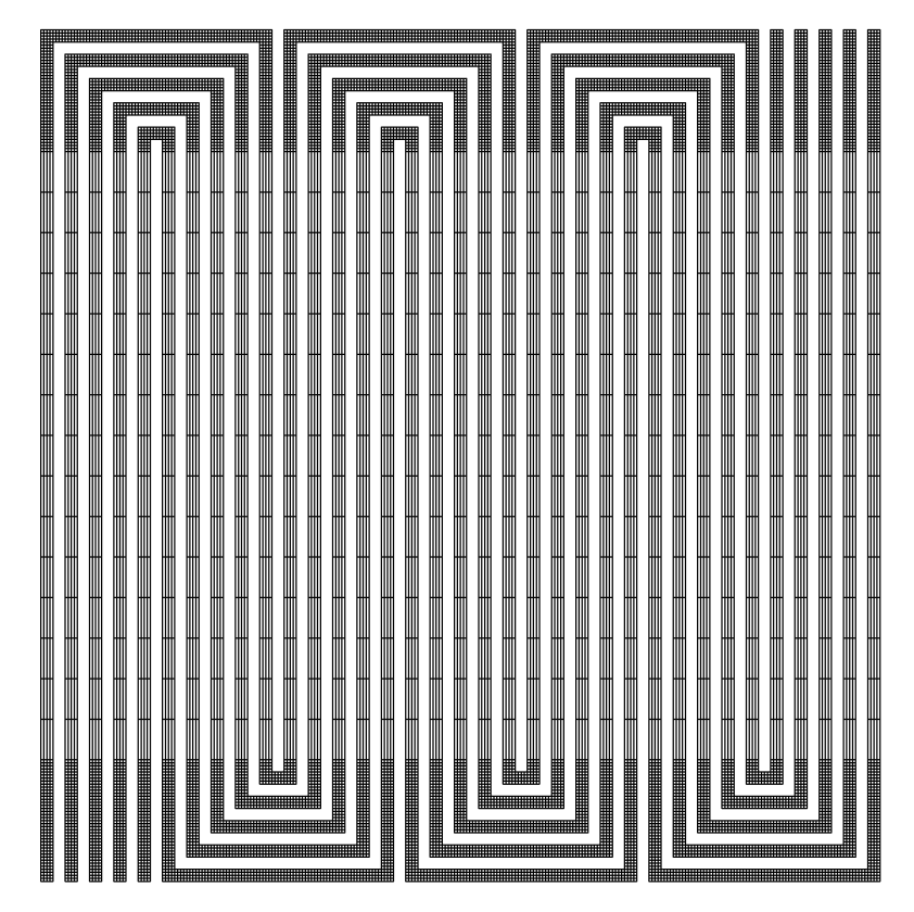 | Figure 4. Mesh pattern used in each cell |
 | Figure 5. The Mesh grids were more refined at the channel bends to analyse the flow pattern |
3.2. Meshing
The process of obtaining an appropriate mesh (or grid) is termed mesh generation (or grid generation), and is a bottleneck in the analysis process due to the lack user friendly mesh generation procedure. The accuracy of the CFD solution is governed by the size of mesh elements in the model. In general, larger the number of mesh elements, the better is the solution accuracy. Both the accuracy of the solution and its cost in terms of necessary computer hardware and calculation time are dependent on the fineness of the grid. Optimal meshes are often non-uniform: finer in areas where large variations occur from point to point and coarser in regions with relatively less change. Also the meshes were checked for inaccuracies in terms of aspect ratio and skewness of the grids. Grid independence test is necessary to arrive at a optimum mesh size.After a series of trial and error approach, the mesh grid size was taken as 0.25*0.25*0.25 limited by the computational facility. The simulation for each operating models for 50 cells and 20 cells took 48 hours to complete, on an Intel Core i7 2.00 GHz PC with 8 GB of DDR3 RAM.
3.3. Boundary Conditions
The boundary conditions for the model is the velocity to be supplied at the inlet which is calculated based on the current density, and the usage of the reactants by the fuel cell stack. Thus the inlet velocity was found out to be 11.852ms-1 for 20 cells and 29.6ms-1 for 50 cells. At the outlet of the manifold, we consider ambient pressure outlet conditions. [13]
4. Results and Discussion
4.1. Analytical Validation
Due to the lack of experimental data, the numerical results were validated analytically from literature. The validation for the air flow (cathode) was carried out on a simple U channel. Model specifications were as follows.- Channel width- 1mm- Channel depth- 1mm- Channel length- 105mm- Air inlet Velocity- 0.47183m/s- Channel active area- 1.56cm2Boundary Conditions were calculated based on the active fuel cell area, required current density and air usage by the fuel cell.The modelling and meshing were done in Gambit 2.4.6 and simulations were carried out on Fluent 12.1. The pressure contours and velocity vectors were generated.Pressure drop from the simulation result was found out to be ΔP =23.257Pa.The analytical pressure drop of the different flow channel geometries was calculated by the following Darcy–Weisbach equation [15],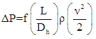 | (3) |
Here, ∆P is the pressure loss due to friction, f is the friction factor, L is the channel length (m), Dh is the hydraulic diameter (m), ρ is the fluid density (air = 1.23 kg m-3), and v is the velocity of the flow (ms−1). For the laminar flow of Re < 2000, the friction factor (f) is defined as, | (4) |
where Re is the Reynolds number defined as, | (5) |
Where ν is the viscosity of the fluid (air =1.81×10⁻⁵ kgm−1s−1). For a rectangular channel with wc as the width and dc as the depth, hydraulic diameter (Dh) is defined as, | (6) |
The pressure difference across the channels were calculated to be ∆P =28.36Pa.By the comparison the results, it was found that the value of pressure difference is lower in the case of theoretical data which is due to the following contradictions. Since the cross section of the channel in the model is square, flow separation tends to occur at the bends and corners which is neglected in the Darcy’s theory. Hence the losses at the bends were not considered in the theoretical calculation. According to the Darcy’s theory, the flow should be steady (fully developed), but in the modelled case, this was not possible. There exists wall friction leading to turbulence effects, which is not accounted in the theory. Also at low velocities both the results were found to be similar. Thus the difference in the solutions were justified.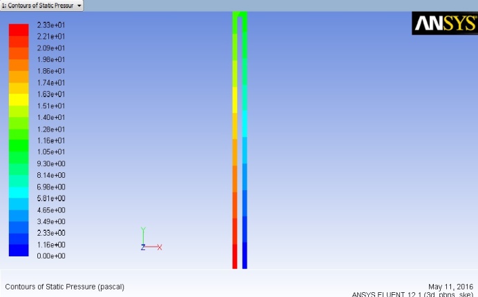 | Figure 6. Pressure Contours |
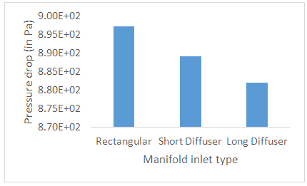
4.2. Influence of Inlet Geometry on Pressure Drop
Pressure drop is being investigated in fuel cell channels design. Along with the flow direction (from inlet to outlet), the pressure drop must decrease; otherwise, reverse pressure drop occurs.High pressure drop indicates the loss that is taking place in the gas channels of the cell, it also causes issues with reactant distribution and causes starvation losses in the cell. Therefore it is best to have the manifold with smallest pressure drop that actually enhances the performance of the fuel cell.By comparing the pressure distribution obtained in the three cases for both 20 and 50 cells, it is found that the pressure drop was least in the case of long diffuser cell stack. This signifies that the manifold geometry affects the pressure drop across the stack. Also it was found that the pressure drop was to decrease with the decrease in the inlet velocity. In turn the dimensional parameters of the manifold were modified to have smaller pressure drop by trial-error method. With the increase in the flow velocity, the turbulence in manifold was increasing which changed the flow patterns. | Figure 7. Pressure drop in 50 cells |
 | Figure 8. Pressure drop in 20 cells |
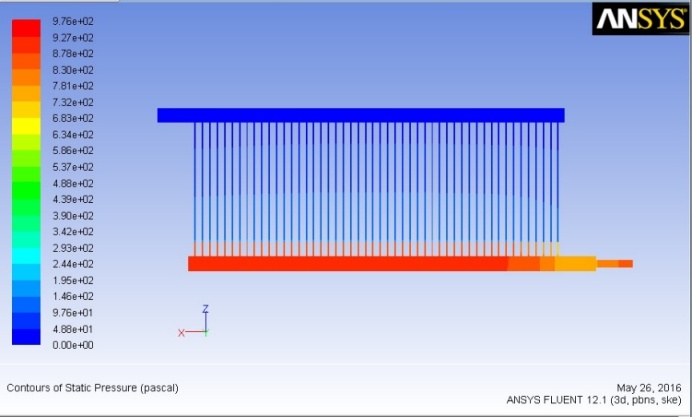 | Figure 9. Pressure contours for 50 cell stack with rectangular inlet |
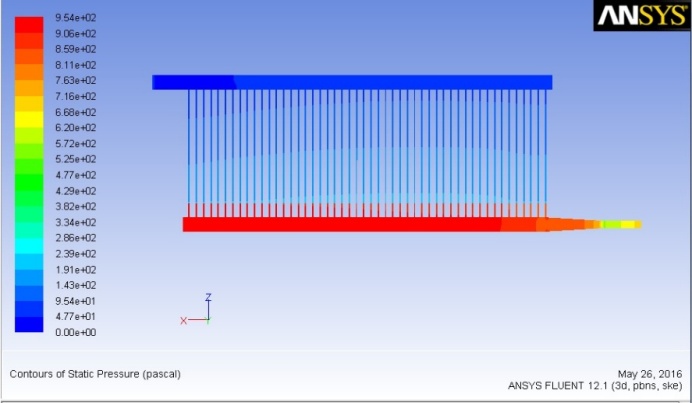 | Figure 10. Pressure contours for 50 cell stack with Long Diffuser inlet |
5. Conclusions
In this study, the effect of inlet manifold geometry on the pressure drop across the PEMFC stack was investigated by CFD considering 3 inlet geometries, but was limited by computation facility. For the design parameters, smooth manifold geometries should be chosen to achieve uniform flow distribution. The arrangements, such as adopting tapering of the manifold cross-section area are feasible for improving the flow distribution.Concerning the operating conditions, both decreasing the inlet velocity the flow distribution will have reduced turbulence and provide a better fuel cell stack performance.In the future work further we can consider the two phase flow (liquid-vapour) and the temperature constraints since the PEMFC exists at 80°C. Also this model can be extended to 200 cells with the membrane electrode assembly and the manifold considering the diffusion and the formation of water and heat dissipation.
References
| [1] | H. Liu, P. Li, Daniel Juarez-Robles, Kai Wang and Abel Hernandez-Guerrero, “Experimental study and comparison of various designs of gas flow fields to PEM fuel cells and cell stack performance” Frontiers in Energy Research, vol. 2, pp. 1-8, 2014. |
| [2] | V. Edupuganti, B. Daglen, “An Investigation of the Impact of the Proton Exchange Membrane Fuel Cell Flow Field Plate Geometry and Design Using Computational Fluid Dynamic Modelling and Simulation” CD-Adapco-Technical Document, 2012. |
| [3] | J. Lebæk, M. Bang and S. K Kær, “Flow and Pressure Distribution in Fuel Cell Manifolds”, J. Fuel Cell Sci. Technol, vol. 7, pp. 1-8, 2010. |
| [4] | S. Pandiyan, A. Elayaperumal, N. Rajalakshmi, K.S. Dhathathreyan, N. Venkateshwaran, “Design and analysis of a proton exchange membrane fuel cells (PEMFC)”, Renewable Energy, vol. 49, pp 161–165, 2013. |
| [5] | C.H. Chena, S. P. Jung, S. C. Yen, “Flow distribution in the manifold of PEM fuel cell stack”, Journal of Power Sources, vol. 173, pp. 249-263, 2007. |
| [6] | R. Govindarasu, R. Parthiban, P.K. Bhaba, “Investigation of Flow Mal-distribution in Proton Exchange Membrane Fuel Cell Stack”, Int. J. Renewable Energy Research, vol. 2, pp. 652-656, 2012. |
| [7] | B. Sreenivasulu, G. Vasu, V. Dharma Rao, and S. V. Naidu, “Effect of Back Pressure and Flow Geometry on PEM Fuel Cell Performance - An Experimental Study”, Int. J. Appl. Sci. Eng., pp. 1-11, 2013. |
| [8] | J. Wang, “Flow Distribution and Pressure Drop in Different Layout Configurations with Z-Type Arrangement”, Energy Science and Technology, vol. 2, pp. 1-12, 2011. |
| [9] | J. Park, X. Li, “Effect of flow and temperature distribution on the performance of a PEM fuel cell stack”, Journal of Power Sources, vol.162, pp 444–459, 2006. |
| [10] | N. W. Freer, “Water management capabilities of bio-inspired flow field configurations for polymer electrolyte membrane fuel cells”, Master Theses, Missouri University of Science and Technology, 2013. |
| [11] | S.G. Kandlikar, Z. Lu, W.E. Domigan, A.D. White, M .W. Benedict, “Measurement of flow maldistribution in parallel channels and its application to ex-situ and in-situ experiments in PEMFC water management studies”, Int. J. Heat and Mass Transfer, vol. 52, pp 1741–1752, 2009. |
| [12] | H. Liu, P. Li, J. V. Lew, “CFD study on flow distribution uniformity in fuel distributors having multiple structural bifurcations of flow channels”, Int. J. Hydrogen Energy, vol. 35, pp. 9186-9198, 2010. |
| [13] | J. Larminie, A. Dicks, “Fuel Cell Systems Explained- Second Edition”, Wiley, 2003. |
| [14] | J. Wang, “Review of Flow mal distribution in channels of PEMFC stacks”, TRRF05 Fuel Cell Technology, December 05, 2009, Lund, Sweden. |
| [15] | Y. C. Park, P. Chippar, S. K. Kim, S. Lim, D. H. Jung, H. Ju, D. H. Peck, “Effects of serpentine flow-field designs with different channel and rib widths on the performance of a direct methanol fuel cell”, Journal of Power Sources, vol. 205, pp 32–47, 2012. |

 Abstract
 Reference
 Full-Text PDF
 Full-text HTML