K. K. Poornesh 1, Chongdu Cho 2, Anil Melwyn Rego 1
1Department of Mechanical Engineering, St Joseph Engineering College, Mangalore, India
2Department of Mechanical Engineering, Inha University, Incheon, South Korea
Correspondence to: K. K. Poornesh , Department of Mechanical Engineering, St Joseph Engineering College, Mangalore, India.
| Email: |  |
Copyright © 2015 Scientific & Academic Publishing. All Rights Reserved.
Abstract
Fuel cell gas diffusion layer (GDL) material design parameters become significant when fuel cell is operated under severe conditions, especially under freeze/thaw cycling. In the previous companion article, theoretical assessment on the anisotropic mechanical properties was established. In order to understand the stability and durability of the whole cell using computational analysis, it is required to precisely understand and know the mechanical property distribution of GDLs. In this study, GDL's anisotropic properties are experimentally determined using taber stiffness units and are compared with the theoretical values. While some GDL types fail to follow, other types are in relative correlation with the theoretically determined values. It is understood that the value prediction through standard theoretical models may not be efficient in determining the actual mechanical property distribution owing to random -to- 3-D distribution of fibers in GDLs.
Keywords:
Fuel Cell, Gas Diffusion Layer, Anisotropy, Taber Stiffness Units
Cite this paper: K. K. Poornesh , Chongdu Cho , Anil Melwyn Rego , Anisotropic Distribution of Elastic Constants in Fuel Cell Gas Diffusion Layers: Experimental Validation, Energy and Power, Vol. 5 No. 1A, 2015, pp. 40-45. doi: 10.5923/c.ep.201501.08.
1. Introduction
Large-scale commercial viability of PEFCs is limited by low durability and high cost. The usage of innovative materials that could meet these two requirements is necessary and highly desirable. In this process, understanding the fundamental physical or electrochemical properties of fuel cell layers becomes inevitable. Thus, experimental and numerical investigation on the durability of GDLs has been an area of active research for several years.In the companion article [1], efforts are made to theoretically predict and understand the anisotropic distribution of mechanical constants in the four GDL types. The prediction of properties are vital as the longevity of GDL might well be dependent on its mechanical response. Han et. al. [2, 3] reported the influence of GDL in-plane anisotropy in bending stiffness on the electrochemical performance of the cell under freezing conditions. They observed that alignment of GDL material direction with respect to the BPP is a critical factor in reducing high frequency resistance and improving the cell performance. In fact, the repetitive cyclic freeze/thaw conditions are believed to cause serious damages to GDL structure as well as its respective interface with CL, owing to the formation of ice lenses during sub-zero temperature [4]. To minimize the durability loss caused by this, researchers have recommended the use of stiffer GDL materials [5, 6]. However, there seem to be procedural evaluation of GDL material properties missing in the literature that can help in understanding the freeze related degradation phenomenon and designing more robust fuel cell systems under severe working conditions. Kleemann et.al. [7] provided a significant insight into the GDL properties by experimentally estimating the vital elastic constants. The flexural moduli were determined using three-point bending method, whereas short-beam bending concept combined with the numerical procedure was employed to estimate the through-plane shear modulus. Since significance of knowing the mechanical properties is crucial to implement suitable GDL for better reliability under severe working conditions of the cell, more convenient and simplified yet reliable solution is necessary that includes basic aspects of material design suitable for the respective cause. Thus, distribution of properties over the entire plane and dependency of through-thickness modulus on the compressive strain needs to be investigated in detail. We propose a possible evaluation technique to obtain all the elastic constants from the Taber stiffness units, which is essentially a bending moment.
2. Experimental
Taber stiffness measurements were performed with a V-5 Model 150-E stiffness tester (Taber industries). Commercial test samples with dimensions of 3.8 cm 7 cm were tested at a bending angle (Θ) of 15° or 7.5° depending on the GDL material type. There are multiple ways to estimate the flexural moduli from the stiffness units (St) and one such method can be referred from the section 3. Another straightforward way is to relate modulus and stiffness units through the following standard equation (more information on this can be found from the user manual of this equipment) and is modified in terms of Pascal units (Pa, Nm-2):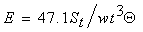 | (1) |
3. Through-Plane Shear Modulus
Though there are multiple techniques available to measure elastic moduli and Poisson’s ratio, evaluation of shear modulus is difficult, especially, through-thickness shear modulus of GDLs. Experimental evaluation of shear modulus of orthotropic composite materials itself is a matter of debate. Thus, very scant information is available on the measurement of through-thickness shear modulus of GDLs. Kleemann et.al [7] suggested a slightly complicated short-beam bending method combined with optimized numerical experiment to measure this property of GDL. A short-beam bending method is primarily used to measure the inter-laminar shear failure influenced by the failure of interface or matrix withholding the fibers. Since the volume fraction of matrix is very less compared to fiber volume fraction in the GDLs, failure usually occurs when the applied load locally exceeds fibers’ strength, and is theoretically explained in the literature reference [8]. This type of failure of GDL fibers can be fairly noted from the experimental observations (e.g., Nitta et.al [9], Lu et.al [10]) where the mixed loading mode (flexural bending combined shearing force) in the vicinity of channel area causes the fracture of fibrous layer. The concept of through-plane shear modulus can thus theoretically be approximated on the background of these explanations with respect to the length to thickness ratio of GDL such that there is a minimal influence of bending. The length to thickness ratio is critical in determining the mode of failure in GDLs. Since the observed failure of GDLs is understood to be due to the coupled effect of shear and flexural failures even at channel width of ~1.3 mm, it is interesting to define the limits on the shear or flexural influence on failure. Thus, flexural to shear strength ratio of GDL in 3-point bending (which imitates the actual loading condition inside the cell) by assuming GDL as a beam is given as: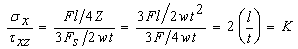 | (2) |
Where F is the force applied to the specimen sample with length l and having a section modulus of Z with thickness t and width w. K is constant parameter and the value of which depends on the σx/τxz ratio. Thus, from above we can now have following limiting factor. Under compression, the GDL will fail in flexure rather than in shear (or flexural failure prior to interlaminar shear failure) if: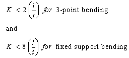 | (3) |
Thus, it is also noted from above equation that, under very small length to thickness ratio, failure is dominated by shear than flexure and at this limit or below, assessment of shear properties is possible with high precision, experimentally. Importance of this relation will be illustrated after obtaining the expressions for flexural and shear strength.In this study, we make use of bending moment, i.e. Taber stiffness units, as the primary source to determine all the necessary parameters including the shear modulus. By approaching this way, we are shifting from simply supported to cantilever beam theory. Compression of the GDL leaves maximum tensile or maximum compressive stress at the surface and the distribution of which is simply given by σm as: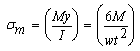 | (4) |
Now the force required to exert this stress can be related to the flexural strength and is given by: | (5) |
The external force also produces the shear stress in the composite beam, which has a parabolic distribution with its maximum value at the mid-plane (unlike normal stress), and is given as: | (6) |
From preliminary calculations, theoretical constant K for 10BC GDL was found to be around 27. Now we choose practical value to calculate the length to thickness ratio. Thus, 8l/t (l = (land width/2) + (channel width/2) = 1.08 mm; t = 0.38 mm) ratio was around 22, meaning the GDL would fail in shear prior to flexure when the compressive force exceeds the maximum shear strength. Since the difference between the two ratios is small, one can expect a coupling effect even at this stage, which may be true in practical cases. What this means to experimental evaluation of shear modulus is that either length has to be decreased or another method shall be approached to find out the actual amount of influence of flexure. In what follows, we estimate total deflection (d) of the GDL to be sum of deflection in flexure (df) and shear (ds), and are simplified to match our experimental conditions as follows: 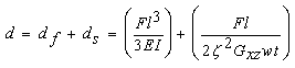 | (7) |
Where ζ is constant, which accounts for non-uniform shear stress distribution through the thickness and the value of which depends on the cross-section shape and poisson’s ratio and can be given as: 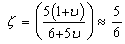 | (8) |
Then ratio of two deflections can be expressed as follows: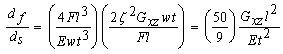 | (9) |
Now, through-plane shear modulus can be given as: 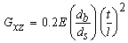 | (10) |
It is noted in this study that Poisson’s ratio of GDLs is taken as zero due to high porosity.
4. Results and Discussion
4.1. In-plane elastic modulus
A plot comprising in-plane elastic constants is shown in Fig. 1. It is observed that the elastic modulus of all the three GDL types in the longitudinal direction is greater than in the transverse direction suggesting a strong to moderate anisotropy in the fiber density distribution. Based on the values obtained here, major classification of GDLs can be made as: high (e.g., 10BC), medium (e.g., 35BC) and low (e.g., 25BC or Carbon Cloth) stiffness GDLs. Though the degree of anisotropy for 35BC is less than 10BC, the long-term cell performance can be dependent on the orientation of GDL with respect to the BPP channel/land network design. It is trivial to notice from the results that if the high modulus GDL orientation is cross-aligned with respect to the major BPP flow field direction, GDL intrusion could be reduced thus increasing its stability. Thus, although it is desirable to have homogeneous GDL material, anisotropy can also be made advantageous depending on its load bearing capacity to the BPP flow field direction. This means to say that though 35BC seems appropriate due to its relatively low anisotropy compared to 10BC, higher stiffness valued GDL becomes a valid choice in its application under severe cell operating conditions.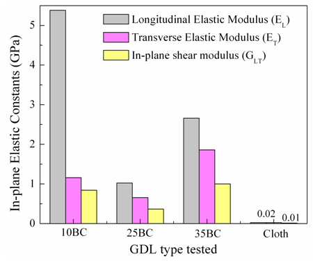 | Figure 1. Values of in-plane elastic constants of major GDL types tested |
As observed from the figure, though carbon cloth GDL has isotropic properties, its application in fuel cell can just be discarded due to very low mechanical properties. Interesting point to be noted here though is that quantitative assessment and comparison of mechanical property distribution would not have been necessary, had the cell operated under normal conditions. Thus, in-plane shear modulus might just become influential design factor in the overall stability of GDL. As we can observe from the figure, in-plane shear modulus of 35BC is relatively higher than any other GDL type owing to its relatively low anisotropy with medium stiffness values. However, role of in-plane shear modulus in GDL design becomes inferior to through-plane shear modulus due to the type of loading that GDL experiences under normal conditions.
4.2. In-Plane Anisotropic Distribution of Properties
Fig. 2 shows the in-plane distribution of elastic modulus for four GDL types at each of θ=10° from θ=0° (longitudinal) to 90° (transverse) orientation. Each plot (Figs. 2(a-c)) except Fig. 2d has three curves, two of which represents the theoretical model approximations of unidirectional fiber and random long fiber composite model. To validate these, experimental results were also included. Since random long fiber model assumes a uniform distribution density, values of in-plane elastic constants would be same in all orientations. Therefore, unidirectional fiber composite theory is believed to explore the in-plane GDL elastic properties in a way much closer to the experimental values. In case of 10BC GDL, since the difference between EL and ET is higher, theory would predict a sudden/rough change in property transitions. Experimental results show a smooth transition in the properties indicating a linear decrease in the fiber density distribution from longitudinal to transverse direction. In case of 35 BC GDL, experimental and theoretical values are nearly similar and follow in close proportion to the random fiber model, indicating a near uniform fiber distribution density.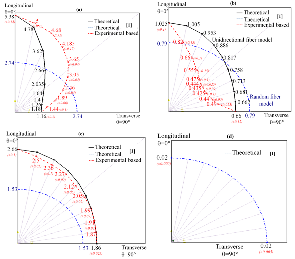 | Figure 2. Estimated theoretical and calculated experimental in-plane elastic modulus distribution maps for (a) 10BC, (b) 25BC, (c) 35BC, (d) cloth |
Fig. 3(a) shows the theoretical and experimental values of normalized elastic modulus as a function of orientation angle. It should be noted that values of Ex is quite dependent on the theoretical prediction of G12 based on EL and ET. Thus, experimental evaluation of G12 would be recommended; however, we shall illustrate with some examples in Appendix that such experimental techniques may not be necessary.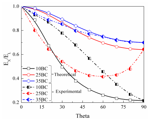 | Figure 3(a). Normalized in-plane elastic modulus of GDLs in terms of distribution angle |
Theoretically, 10BC GDL exhibits high anisotropy as opposed to other types. Experimental observation indicates a proportional variation in the elastic modulus with respect to theoretical values except for 25BC. In case of 25BC, variation is unpredictable, i.e., distribution is highly nonlinear. Further, in-plane shear moduli are plotted as shown in Fig. 3(b). Theoretical prediction illustrates a maximum shear modulus at θ=45° for all the three GDLs with a minimum value occurring at θ=0° and 90°.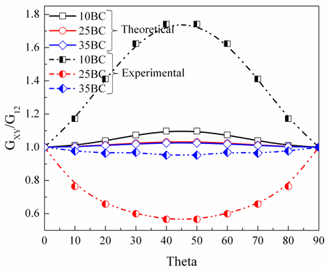 | Figure 3(b). Normalized in-plane shear modulus of GDLs in terms of distribution angle |
The degree of transition of elastic modulus from longitudinal to transverse orientation is reflected in these theoretical curves. However, curves plotted from the experimental values show a high degree of difference with the theoretical ones. Appearance of maximum shear modulus at θ=0 and 90 and minimum at θ=45 for 25BC and 35BC GDLs is unusual and it is a direct reflection of elastic modulus variation plotted for these materials as in Fig. 2(a) and (c). Thus, theoretical curve in Fig. 3(a) provides a limiting factor of design. If the experimental plot of elastic modulus for GDL falls above this zone, then that GDL material can be preferred over other GDL types that fall decisively within this limit.
4.3. Through-Plane Shear Modulus
This property of GDLs is evaluated on the principle of interlaminar shear strength of fiber composites as explained in the section 3. Basic ingredients for estimating through-plane shear modulus are obtained from the experiment, such as applied force (derived from the Taber stiffness units), total sample deflection and sample dimensions. Fig. 4 shows the through-thickness shear modulus as a function of in-plane fiber orientation for the three types of GDLs. It is observed that the through-thickness shear modulus of 10BC GDL is higher in the longitudinal plane as compared to other GDL types, but it exhibits strong anisotropic distribution of values as a function of in-plane fiber orientation (~20MPa to 4MPa). Difference between longitudinal and transverse directional through-plane shear modulus is negligible in case of 25BC (~5MPa) and 35BC (~8MPa) GDLs. The values obtained here might deviate a bit from those obtained from experimental methods but even these experimental approaches are not exact or error proof, given the GDL’s very low thickness and high deformation to external load.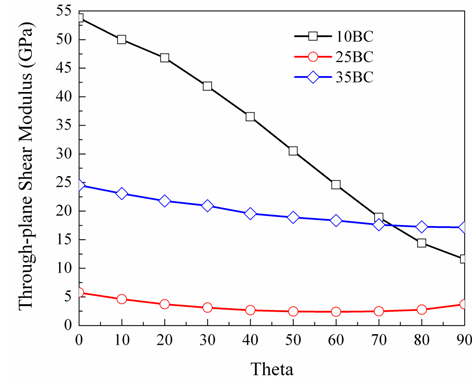 | Figure 4. Values of through-plane shear modulus in terms of distribution angle for different GDLs |
5. Conclusions
The three types of GDLs used for this study are classified as high (10BC (felt)), medium (35BC (paper)) and low stiffness (25BC (paper), Cloth) GDLs based on the magnitude of flexural modulus. The major conclusion drawn from this study is that the anisotropy in GDLs is not only limited to principal material directions but also it is evident in all the fiber orientation directions with its magnitude and nonlinearity depending on the fiber volume fraction. Of the three GDLs, 35BC is observed to have low anisotropy as compared to 10 BC, though the longitudinal modulus of the latter is much higher making 10BC a valid choice under fuel cell working conditions. The two models, based on unidirectional composite and random long fiber composite theory, are compared with the experimentally obtained values of in-plane elastic constants. In order to minimize experimental effort, some reasonable suggestions were also made. However, it is recommended to follow experimental procedure as questions may arise on the validity of these models to other GDLs as there might be higher or lower values of elastic constants other than in the principal directions (that is, other than θ=0° and θ=90°). For example, one can have following inequalities with respect to Ex to check whether there would be any extremum value. The Ex will be less than both E1 and E2 for some values of θ other than principal directions if: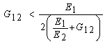 | (11) |
On the other hand, Ex will be greater than both E1 and E2 for some values of theta other than principal directions if: | (12) |
We can see that these inequalities hold valid to all tested GDLs except in case of 25BC where experimental values of elastic constants are far lesser to E2 (Fig. 2), thereby violating inequality Eq. (12).Through-thickness modulus is one of the major parameters involved in the design of stable GDLs. The nonlinear response induced in the GDL during the initial loading has its dependence on the dimensional distribution of fibers. This type of nonlinearity can be regarded as a settling phase for the GDL, thus modulus taken at this stage may not have a significant influence on the overall response of the GDL. Nevertheless, not all GDLs show this typical behavior, for example, 10BC GDL (it is a felt GDL) shows near linear response to the compressive load. After analyzing the data with respect to the change in through-plane resistance, in-plane permeability and thickness as a function of compressive load, we could attribute this initial nonlinear behavior to the fiber buckling and stretching of the interface matrix. The GDL material design parameters become significant when fuel cell is operated under severe conditions, especially under freeze/thaw cycling. Further, results obtained here can widely be applied in three-dimensional structural analysis of cell emphasizing on the GDL response with respect to other cell components, which is useful in understanding its stability and durability.
ACKNOWLEDGEMENTS
This work is supported by Inha University, South Korea and St. Joseph Engineering College, Mangalore, India.
References
| [1] | K. K. Poornesh, B. Chirant, A.M. Rego, Neil Vaz, Anisotropic Distribution of Elastic Constants in Fuel Cell Gas Diffusion Layers: Theoretical Assessment, ETIME Conference, Mangalore 2015. |
| [2] | K. Han, B. K. Hong, S. H. Kim, B. K. Ahn, T. W. Lim, Influence of anisotropic bending stiffness of gas diffusion layers on the electrochemical performances of polymer electrolyte membrane fuel cells, Int J of Hydrogen Energy 35 (2010) 12317 – 12328. |
| [3] | K. Han, B. K. Hong, S. H. Kim, B. K. Ahn, T. W. Lim, Influence of anisotropic bending stiffness of gas diffusion layers on the degradation behavior of polymer electrolyte membrane fuel cells under freezing conditions, Int J of Hydrogen Energy 36 (2011) 12452 – 12464. |
| [4] | S-J Lim, G-G Park, J-S Park, Y-J Sohn, S-D Yim, T-H Yang, B K Hong, C-S Kim, Investigation of freeze/thaw durability in polymer electrolyte fuel cells, Int J of Hydrogen Energy 35 (2010) 13111-13117. |
| [5] | S. Kim, M.M. Mench, Physical degradation of membrane electrode assemblies undergoing freeze/thaw cycling: Micro-structure effects, Journal of Power Sources 174 (2007) 206–220. |
| [6] | S. Kim, B. K. Ahn, M.M. Mench, Physical degradation of membrane electrode assemblies undergoing freeze/thaw cycling: Diffusion media effects, Journal of Power Sources 179 (2008) 140–146. |
| [7] | J. Kleemann, F. Finsterwalder, W. Tillmetz, Characterisation of mechanical behaviour and coupled electrical properties of polymer electrolyte membrane fuel cell gas diffusion layers, Journal of Power Sources 190 (2009) 92-102. |
| [8] | K.K. Poornesh, C.D. Cho, G.B. Lee, Y.S. Tak, “Gradation of mechanical properties in Gas Diffusion Electrode – Part 2 Heterogeneous carbon fiber and damage evolution in cell layers, Journal of Power Sources 195 (2010) 2718-2730. |
| [9] | I. Nitta, O. Himanen, M. Mikkola, Thermal Conductivity and Contact Resistance of Compressed Gas Diffusion Layer of PEM Fuel Cell, Fuel Cells 08 (2008) No. 2, 111–119. |
| [10] | Z. Lu, C. Kim, A. M. Karlsson, J. C. Cross, M. H. Santare, Effect of gas diffusion layer modulus and land–groove geometry on membrane stresses in proton exchange membrane fuel cells, Journal of Power Sources 196 (2011) 4646-4654. |
 Abstract
 Reference
 Full-Text PDF
 Full-text HTML