K. K. Poornesh , Chiranth B. P. , Neil Vaz, Anil Melwyn Rego
Department of Mechanical Engineering, St Joseph Engineering College, Mangalore, India
Correspondence to: K. K. Poornesh , Department of Mechanical Engineering, St Joseph Engineering College, Mangalore, India.
| Email: |  |
Copyright © 2015 Scientific & Academic Publishing. All Rights Reserved.
Abstract
Stability of gas diffusion layers (GDLs) in polymer electrolyte fuel cells (PEFCs) becomes critical under severe working conditions, especially during freeze/thaw and dry/wet cyclic loadings. Thus, evaluation of adaptability of GDLs (Gas diffusion media and Micro-porous layer) becomes an integral design factor for its efficient performance. In this article, we report on the anisotropic distribution of mechanical properties of GDLs (felt, paper and cloth type), based on predictive theoretical techniques. Evaluation of in-plane (longitudinal and transverse) elastic and in-plane shear modulus becomes necessary to assess the in-plane stability, which is influenced by fiber bending and sliding. Through-plane shear modulus of GDLs is theoretically estimated based on the inter-laminar shear strength by which one can omit the use of separate experimental combined numerical approach.
Keywords:
Fuel Cell, Gas Diffusion Layer, Anisotropy, Through-Plane Shear Modulus
Cite this paper: K. K. Poornesh , Chiranth B. P. , Neil Vaz, Anil Melwyn Rego , Anisotropic Distribution of Elastic Constants in Fuel Cell Gas Diffusion Layers: Theoretical Assessment, Energy and Power, Vol. 5 No. 1A, 2015, pp. 34-39. doi: 10.5923/c.ep.201501.07.
1. Introduction
The GDL in a polymer electrolyte fuel cell plays a multifunctional role that includes transportation of reactant gases, electron conduction, providing structural support and management of water product. A typical GDL consists of highly macroporous carbon fiber based supports (paper, cloth or felt) with the MPL (micro-porous layer) backing. Thus, the GDL is fundamentally a carbon-carbon fiber oriented in random material directions with high porosity making it to the category of random long fiber composites. One of the major factors for GDL instability in the working cell is an uneven compression as documented by several researchers [1-5]. A high degree of compression may significantly affect the porosity distribution causing water management problems, and uneven compression may lead to fiber breakage and deterioration of hydrophobic coatings [4]. Thus, longevity of GDL might well be dependent on its mechanical response. Thus, as the researches on the innovative GDLs are progressing with a rapid pace, it becomes necessary to develop and adopt simple techniques to estimate the physical properties for their characterization.
2. Theoretical Assessment
Here, we outline the approaches used to estimate the elastic constants from the fundamentals of mechanics. A one-to-one relationship between the state of stress and the state of strain in elastic body undergoing deformation upon the action of external forces is generally expressed by the linear relation that relates nine components of stress to the nine components of strain, and is given by: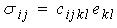 | (1) |
where, σij, ekl, cijkl are the true stress components, infinitesimal strain components, and material parameters respectively. Thus it would require 81 parameters (3n; n=tensor rank) to characterize a material fully. However owing to the symmetry (σij = σji; ekl = elk) and strain energy density considerations (cij=cji) it can be proved that for an anisotropic elastic body, requirement of elastic parameters reduces to 21. This is to say that elastic moduli relating the components of stress (or strain) depend on the orientation of the coordinate system for an anisotropic material. For an isotropic material, cij becomes independent of orientation as it consists of infinite number of symmetry planes. Thus for isotropic materials, stress-strain relationship is given by: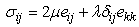 | (2) |
where µ (also referred as G, shear modulus) and λ are Lame constants which are related to E (elastic modulus) and υ (Poisson’s ratio). Thus, isotropic material is defined by just two elastic parameters. A material is said to be orthotropic whenever the three mutually orthogonal planes of elastic symmetry exist. This will reduce the number of independent elastic constants from 21 to 9 as various stiffness and compliance terms are interrelated. The strain-stress relationships in terms of engineering constants are then expressed as: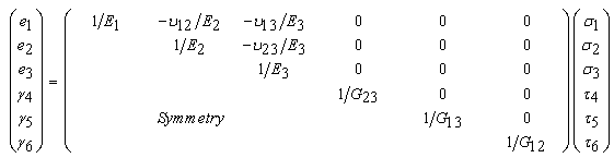 | (3) |
where, E1, E2, E3 are elastic moduli in 1 (longitudinal), 2 (transverse), and 3 (through-plane) directions, respectively. υij is Poisson’s ratio (-ej/ei). G23, G13, G12 are shear moduli in the 2-3, 1-3, and 1-2 planes, respectively. Let us assume GDL to be unidirectional composite (Fig. 1 schematically depicts the in-plane fiber distribution in major types of composite structures) having three mutually perpendicular planes of symmetry (fully orthotropic). 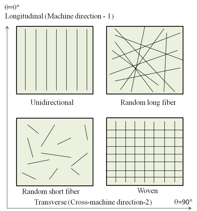 | Figure 1. Schematic representation of major classes of fiber (unidirectional, random long fiber, random short fiber, and woven) composites based on fiber distribution in terms of longitudinal and transverse principal direction |
Since we are interested in mapping the in-plane directional properties of GDL, plane stress condition can be invoked (that is, GDL is assumed sufficiently thin that the through-thickness stresses are zero). This would simplify Eq. (3) leaving only 4 elastic constants to be defined.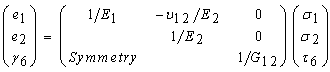 | (4) |
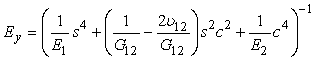
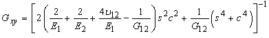
It is noted here that, normal stresses do not influence shearing strains and shearing stresses do not cause extensional strains. Thus, there exists no coupling between normal and shear strains, but this may not be so when the GDL is tested at arbitrary angles to the principal material directions. Thus, consider the GDL tested at an angle θ with the new coordinate system x-y to the principal material directions. It is possible now to express elastic properties corresponding to new x-y coordinate system as follows [6-8]: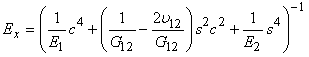 | (5) |
 | (6) |
 | (7) |
where, s = sinθ and c=cosθ.Thus once we have experimental values of E1 (longitudinal or machine direction modulus = EL), E2 (transverse or cross-machine direction modulus = ET) and G12 (in-plane shear modulus), elastic properties at any angular direction can be estimated. However, a typical GDL may not belong to the class of a unidirectional composite material as it is normally referred on par with the long fiber random composite material. Since there are varieties of GDLs available today, it is a difficult to classify under a particular class. Thus, by comparing the properties of both the composite types we can estimate on the property variation and class of GDLs in relation to the conventional composites. A typical random long fiber composite is thought to have isotropic in-plane properties if the probability of random fiber distribution is uniform in the in-plane direction. Thus, it follows that effective modulus (or shear modulus) of such composite can be obtained by integrating Ex (or G12) (Eq. (6)) over 0° to 90° which is expressed as: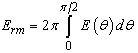 | (8) |
Simplified form of above expression is given for Erm and Grm is given by [8]: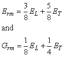 | (9) |
Since longitudinal and transverse modulus is obtained experimentally in this study, any further theoretical evaluation of these moduli is avoided. It is noted that through-plane shearing of the fuel cell GDL is more obvious than the in-plane shearing due to the nature of compressive loading. Apart from this, it is always difficult to produce pure shear effect in the GDL by experimental means in order to assess the shear properties as there would be coupling effect induced by the flexure. In mathematical sense, we would like to proceed to this from the material isotropy. It was stated above that for an orthotropic material, 3-dimensional stress-strain relations would require nine independent elastic constants and 2-dimensional relations require four constants (plane stress or plane strain case). It was also briefed that for an isotropic material it would require only two constants as the shear modulus is related to these parameters as follows: 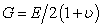 | (10) |
Thus, need for experimental evaluation of shear modulus for isotropic materials may not arise. However, the introduction of orthotropy to the material will alter the shear modulus, G. Hence, above relationship begins to fall apart for orthotropic material, as there would be difference among properties in the orthogonal planes, meaning G would gradually become independent of elastic modulus and Poisson’s ratio. Thus for orthotropic materials, as in case of the GDLs, independent evaluation of four (in 2D) or nine (in 3D) elastic constants is generally recommended. Since the in-plane shear stresses are not directly generated by normal stresses, importance of in-plane shear modulus as a design parameter might depend on the interface friction and internal sliding of the fibrous layers of the GDL. In addition, it is interesting to mention here that there exist few relations, which can become useful in estimating the in-plane shear modulus of an orthotropic material. They are given as follows: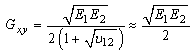 | (20) |
or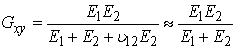 | (21) |
However, we find that if the difference between the two moduli is more than the order of two, the above relations fail to validate experimental values, especially Eq. (20) (note that, these equations, though seem approximations, are better substitution for complex experimental combined numerical approaches to estimate the in-plane shear modulus of GDL. These relations are validated against the experimental values for orthotropic structures and are tabled in the Appendix). Hence, in estimating the through-thickness modulus these equations may not be useful. In contrary, we apply Eq. (21) to approximate the in-plane shear modulus of GDL.
3. Results and Discussion
3.1. In-Plane Elastic Modulus
In-plane (longitudinal and transverse) flexural moduli are first evaluated for four GDL types by experimentally obtaining the Taber stiffness units (bending moment) as discussed in our companion article [13] and is plotted in Figure 2 as a reference. Figure 3 shows in-plane distribution of elastic modulus for four GDL types at each of θ=10° from θ=0° (longitudinal) to 90° (transverse) orientation. Each plot (Figs. 3(a-c)) except Fig. 3d has two curves, which represents the theoretical model approximations of unidirectional fiber and random long fiber composite model. Since random long fiber model assumes a uniform distribution density, values of in-plane elastic constants would be same in all orientations. Therefore, unidirectional fiber composite theory is believed to explore the in-plane GDL elastic properties in a way much closer to the experimental values which has to be validated.To better illustrate the variation of elastic constants, they are plotted as functions of orientation θ. Fig. 4(a) shows the theoretical values of normalized elastic modulus as a function of orientation angle. It should be noted that values of Ex is quite dependent on the theoretical prediction of G12 based on EL and ET. Thus, experimental evaluation of G12 would be recommended; however, we shall illustrate with some examples, as mentioned Appendix, that such experimental techniques may not be necessary.Further, in-plane shear moduli are plotted as shown in Fig. 4(b). Theoretical prediction illustrates a maximum shear modulus at θ=45° for all the three GDLs with a minimum value occurring at θ=0° and 90°. The degree of transition of elastic modulus from longitudinal to transverse orientation is reflected in these theoretical curves.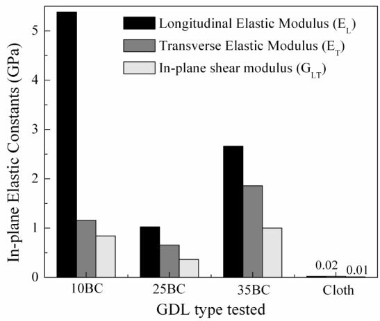 | Figure 2. Values of in-plane elastic constants of major GDL types tested |
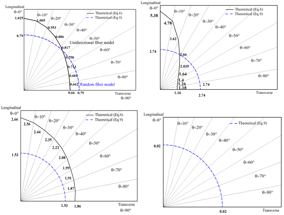 | Figure 3. Estimated theoretical in-plane elastic modulus distribution maps for (a) 10BC, (b) 25BC, (c) 35BC, (d) cloth |
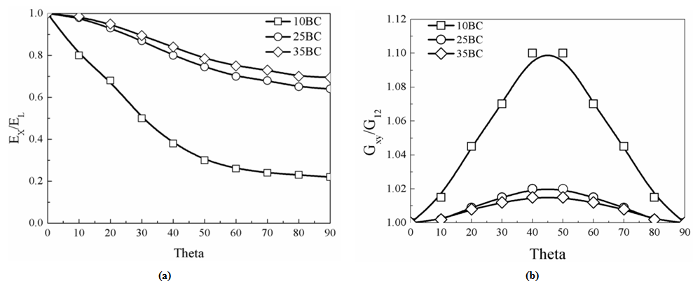 | Figure 4. Normalized in-plane elastic modulus of GDLs in terms of distribution angle |
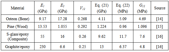
Table 1. Elastic constants of some orthotropic materials
 |
| |
|
4. Conclusions
In this article, distribution of mechanical properties of four types of GDL material is theoretically predicted. It is expected that the property distribution is anisotropic and hence the two theoretical models are tested with the prior knowledge of longitudinal and transverse modulus which are experimentally derived. Based on the principle of interlaminar shear strength of fiber composites, anisotropic distribution of through-plane shear modulus was mapped. In order to estimate the in-plane shear modulus, simple theoretical relations are adopted which are tested for other materials as listed in Appendix. The experimental method and validation of theoretical values of the present work is presented in the companion article [13].
Appendix
Here, Eq. (20) and Eq. (21) will be put to test with the experimental shear modulus values of known materials. Table 1 shows the basic elastic constants, Poisson’s ratio, theoretical value and experimental value of selected orthotropic materials. It can be seen that both of these equations give reasonable value of shear modulus that is closer to the experimental values, except in the case of Graphite/epoxy composite system where Eq. (20) fails to evaluate any closer to the experimental value as the difference between the two moduli is more than the order of two. Therefore, we preferred Eq. (21) to evaluate in-plane shear modulus.
ACKNOWLEDGEMENTS
This work is supported by St. Joseph Engineering College, Mangalore, India.
References
| [1] | S.G. Kandlikar, Z. Lu, T.Y. Lin, D. Cooke, M. Daino, Uneven gas diffusion layer intrusion in gas channel arrays of proton exchange membrane fuel cell and its effects on flow distribution, J of Power Sources, 194 (2009) 328-337. |
| [2] | I. Nitta, T. Hottinen, O. Himanen, M. Mikkola, Inhomogeneous compression of PEMFC gas diffusion layer Part I. Experimental, Journal of Power Sources 171 (2007) 26–36. |
| [3] | J-H Lin, W-H Chen, Y-J Su, T-H Ko, Effect of gas diffusion layer compression on the performance in a proton exchange membrane fuel cell, Fuel 87 (2008) 2420-2424. |
| [4] | A. Bazylak, D. Sinton, Z.-S. Liu, N. Djilali, Effect of compression on liquid water transport and microstructure of PEMFC gas diffusion layers, Journal of Power Sources 163 (2007) 784–792. |
| [5] | M. Mathias, J. Roth, J. Fleming and W. Lehnert, Diffusion media materials and characterization, Handbook of Fuel Cells – Fundamentals, Technology and Applications, Volume 3: Fuel Cell Technology and Applications, John Wiley & Sons, Ltd (2003). |
| [6] | I. M. Daniel, O Ishai, Engineering Mechanics of Composite Materials, Oxford University Press (1994). |
| [7] | D. Hull, An Introduction to Composite Materials, Cambridge University Press (1981). |
| [8] | B.D. Agarwal and L.J. Boutman, Analysis and Performance of Fiber Composites, John Wiley & Sons, New York (1980). |
| [9] | J. Kleemann, F. Finsterwalder, W. Tillmetz, Characterisation of mechanical behaviour and coupled electrical properties of polymer electrolyte membrane fuel cell gas diffusion layers, Journal of Power Sources 190 (2009) 92-102. |
| [10] | K.K. Poornesh, C.D. Cho, G.B. Lee, Y.S. Tak, “Gradation of mechanical properties in Gas Diffusion Electrode – Part 2 Heterogeneous carbon fiber and damage evolution in cell layers, Journal of Power Sources 195 (2010) 2718-2730. |
| [11] | I. Nitta, O. Himanen, M. Mikkola, Thermal Conductivity and Contact Resistance of Compressed Gas Diffusion Layer of PEM Fuel Cell, Fuel Cells 08 (2008) No. 2, 111–119. |
| [12] | Z. Lu, C. Kim, A. M. Karlsson, J. C. Cross, M. H. Santare, Effect of gas diffusion layer modulus and land–groove geometry on membrane stresses in proton exchange membrane fuel cells, Journal of Power Sources 196 (2011) 4646-4654. |
| [13] | K. K. Poornesh, C.D. Cho, A.M. Rego, Anisotropic Distribution of Elastic Constants in Fuel Cell Gas Diffusion Layers: Experimental Validation, ETIME Conference, Mangalore 2015. |
| [14] | G. Franzoso, Elastic Anisotropy of Lamellar Bone Measured by Nanoindentation, Doctoral Thesis, Politecnico Di Milano (2008). |
| [15] | J. L. Morais, J. C. Xavier, N.M. Dourado, J.L. Lousada, Mechanical behavior of wood in the orthotropic directions, Proceedings of the 1st international conference of the European society for wood mechanics, Swiss Federal Institute of Technology Lausanne (EFPL) (2001) 355–363. |
| [16] | D. Roylance, Laminated composite plates, MIT, Cambridge (2000). |
 Abstract
 Reference
 Full-Text PDF
 Full-text HTML