-
Paper Information
- Next Paper
- Previous Paper
- Paper Submission
-
Journal Information
- About This Journal
- Editorial Board
- Current Issue
- Archive
- Author Guidelines
- Contact Us
Electrical and Electronic Engineering
p-ISSN: 2162-9455 e-ISSN: 2162-8459
2015; 5(1A): 7-13
doi:10.5923/c.eee.201501.02
Investigations on Characteristics of Metamaterial Based Patch Antenna for RF Energy Harvesting at GSM 900
 Abstract
 Reference
 Full-Text PDF
 Full-text HTML
K. A. Devi1, C. H. Ng1, C. F. Kwong1, C. K. Chakrabarty2, Norashidah Md. Din2
1Faculty of Science, Technology, Engineering and Mathematics, INTI International University
2Centre for RF and Microwave Engineering, College of Engineering, Universiti Tenaga Nasional
Correspondence to: K. A. Devi, Faculty of Science, Technology, Engineering and Mathematics, INTI International University.
| Email: |  |
Copyright © 2015 Scientific & Academic Publishing. All Rights Reserved.
In this work, a 5 x 5 metamaterial array split ring resonator is introduced onto a C -shaped rectangular patch antenna with a defective ground plane. The patch antenna was designed to operate at the downlink radio frequency band of GSM 900 with a pair of bevel shaped structure and a horizontal slot on top which was closely put at the center of the patch. The objective of this paper is to investigate the effect of metamaterial and the orientation of DSRRs with strip lines behind on the characteristics of patch antenna keeping in view of maintaining the bandwidth, return loss and ameliorating in gain. The results indicates that the amelioration in impedance bandwidth was 23.33% (77 MHz), gain of 44.4% (0.993 dB) and increase in return loss of 19% (6.71 dB ) when compared to the conventional patch antenna.
Keywords: Metamaterial, C-shaped patch, Defective ground plane, Downlink, GSM 900, Impedance bandwidth, Gain
Cite this paper: K. A. Devi, C. H. Ng, C. F. Kwong, C. K. Chakrabarty, Norashidah Md. Din, Investigations on Characteristics of Metamaterial Based Patch Antenna for RF Energy Harvesting at GSM 900, Electrical and Electronic Engineering, Vol. 5 No. 1A, 2015, pp. 7-13. doi: 10.5923/c.eee.201501.02.
Article Outline
1. Introduction
- Microstrip patch antennas are being widely used in wireless communication systems due to their simplicity, but have drawbacks of low gain and narrow bandwidth. Several techniques have been proposed: Increasing the height of substrate and decreasing its permittivity [1], different types of feeding [2], introducing patch antenna with a diamond slot [3], ring [4], ice cone [5], E shaped [6], stepped [7] slots and bevel shape [8]. Another advanced approach is to introduce metamaterial superstrate onto the antenna structure. Feature of metamaterial has also been used in military applications, super lens, sensor, and biomedical applications. The property of negative permittivity and permeability in metamaterials can improve the radiation efficiency of the antenna and provide improvements on gain and radiation characteristic when it acts as a superstrate on an antenna. The basic proposed metamaterial structures found in literature are symmetrical-ring, circular, omega and S [9]. Also in recent years other structures such as fishnet, EBG structure [10] planar patterned array [11] and frequency selective surface [12] were introduced in various applications.These show that the metamaterial can be used as a superstrate, substrate or directly printed onto the patch antenna to achieve gain and bandwidth enhancement whilst miniaturizing the size of the antenna In this article the antenna designed has novelty in determining a specific orientation (180 degree) of DSRRs along with strip lines to obtain better performance in the desired frequency band prior to introduce onto the patch antenna. In addition the double negative properties of the superstrate are verified from the S-parameters. The special features are in superstrate orientation, the verification of double negative properties from S-parameter and the frequency of operation (downlink radio frequency range of GSM 900) which all differs from the previous work.Sections 2 describe the antenna design. Section 3 describes the methodology used. Section 4 describes the analysis on properties of superstrate. Section 5 describes the results obtained and section 6 is the conclusion.
2. Antenna Design
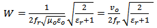
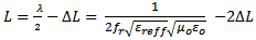
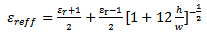
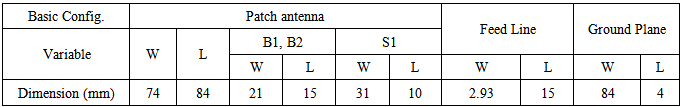
- The configuration of the proposed antenna structure is shown in Figure 1(a) and 1(b). The design structure consists of three layers which are: a C-shaped patch with a defective ground plane, an air gap and a superstrate layer. In the simulation study, the antenna was designed on a FR4 substrate with a 1.6 mm thickness. The copper used is a lossy metal with an electric conductivity of 5.8 × 10⁷ S/m and the permittivity of the epoxy glass substrate is 4.7 with a loss tangent of 0.025. The patch antenna consists of two bevels and a horizontal slot, which is denoted by B1, B2 and S1, which are printed at the top of the substrate and the defective ground plane on the other side. The horizontal slot is used to control the resonant frequency and help to reduce the size of the patch antenna. A partial ground plane with a notch on it at the bottom side of the substrate is used to enhance the impedance bandwidth. The width (W), length (L) and the effective dielectric constant ε_reff of the patch antenna are determined using the equations (1), (2) and (3), which was obtained from [13].
 | (1) |
 | (2) |
 is given by
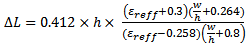 | (3) |
 | (4) |
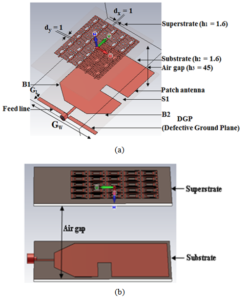 | Figure 1. Proposed antenna: (a) Configuration (b) Side view |
|
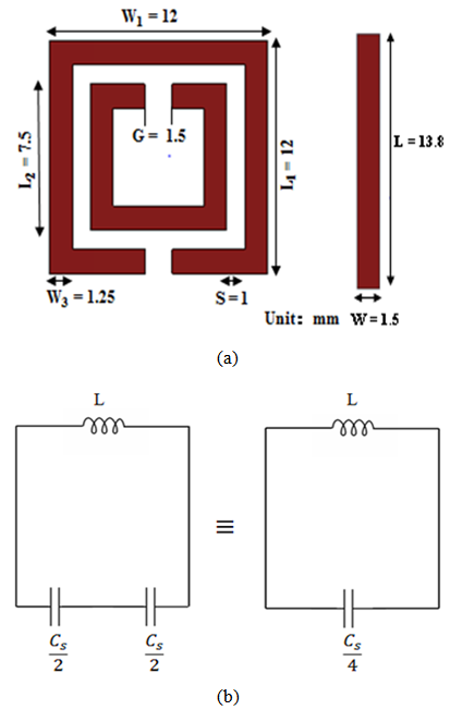 | Figure 2. DSSR (a) Geometry along with strip line (b) Equivalent circuit [14] |
3. Methodology
- The proposed antenna with and without the superstrate structure was designed, simulated and optimized using the time domain solver of the Computer Simulation Technology (CST) microwave studio, version 14. First the patch antenna was designed and simulated at the downlink radio frequency range of GSM 900 band. After that the superstrate layer was designed, simulated for double negative properties and optimized for the desired frequency band. Next the superstrate is introduced onto the patch antenna with an air gap between them. In order to achieve the objectives of the proposed antenna the structure of the antenna, superstrate layer and the air gap between them were optimized by using parametric optimization in CST at the desired frequency band.
4. Analysis on Properties of Superstrate
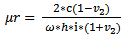
- The structure of the superstrate array 5 × 5 DSRRs along with the strip lines was simulated for various orientations at 0, 90, 180 and 270 degree in order to get better transmission (S21) and reflection (S11) coefficients. The S-parameter results obtained are used to verify the dual negative characteristics (µr and εr) of the superstrate in the desired frequency band.The results of the analysis indicated that better performance was obtained when the superstrate orientation was at 180 degree and its schematic is shown in Figure 3. In this design Nicolson-Ross-Weir (NRW) method [15] was used to verify the double negative properties of superstrate and the values of the permeability and relative permittivity are computed using equations (5) and (6).
 | (5) |
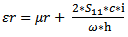 | (6) |

 h = Thickness of the substrate,c = Speed of light,
 μr = Relative permeability,εr = Relative permittivity.
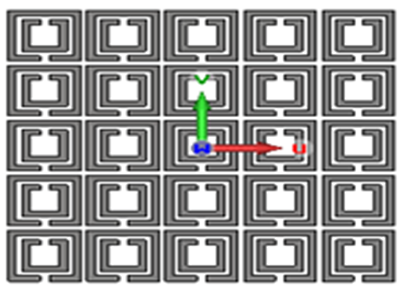 | Figure 3. Schematic of 5 × 5 DSRR superstrate layer oriented at 180 degree |
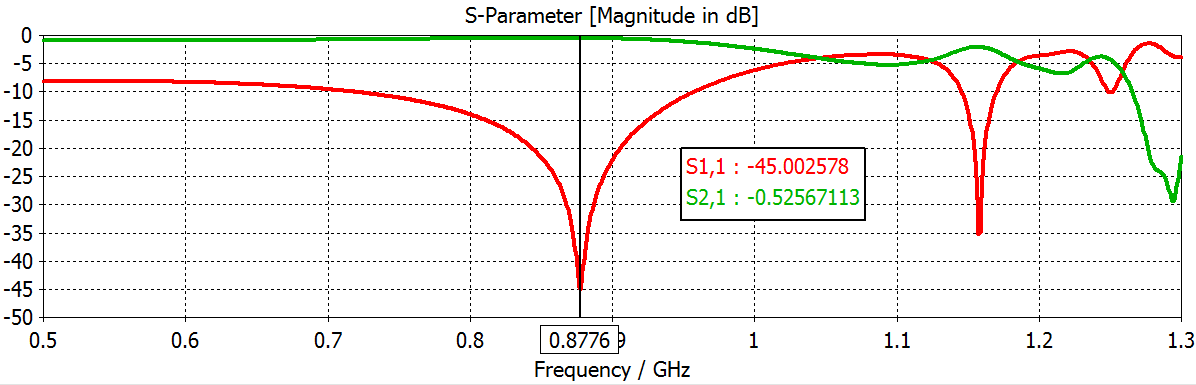 | Figure 4. Transmission and reflection coefficients for 5 × 5 DSRR superstrate oriented at 180 degree |
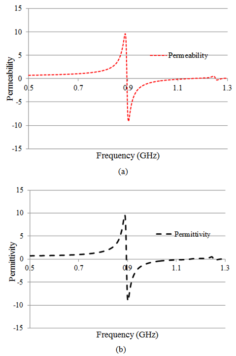 | Figure 5. 5 × 5 DSRR superstrate layer for orientation at 180 degree, (a) Permeability (b) Permittivity |
5. Results and Discussions
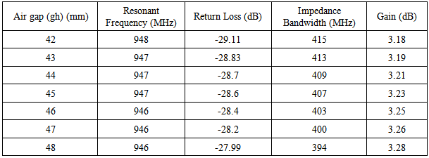
- The results of the return loss for different heights (gh) of the air gap are shown in Figure 6 and its performance was shown in Table 2. Comparison of the results shown that the resonant frequency at an air gap of 45 mm is close to the centre radio frequency (947.5 MHz) of the desired frequency band.
|
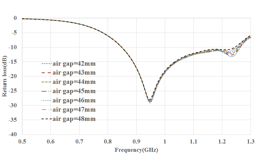 | Figure 6. Comparison of return loss of proposed patch antenna with different air gaps between patch and superstrate |
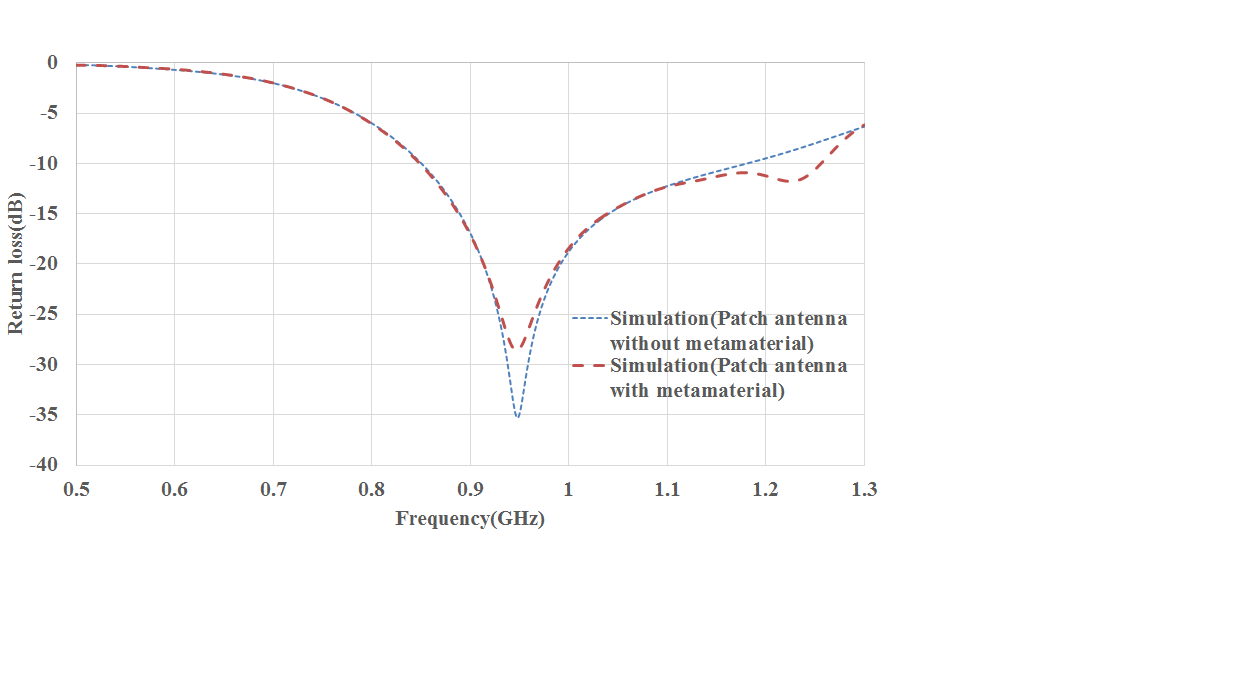 | Figure 7. Comparison of return loss for the proposed antenna with and without metamaterial |
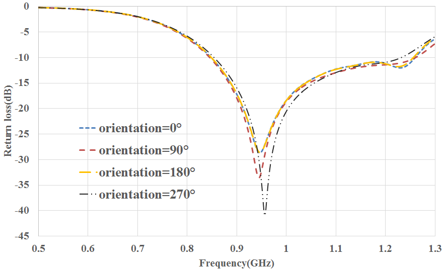 | Figure 8. Comparison of return loss of the proposed superstrate at different orientations |
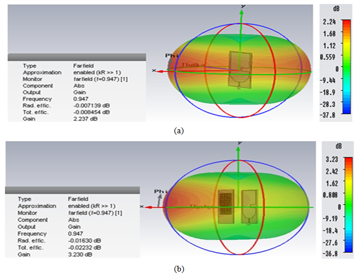 | Figure 9. 3D Gain radiation pattern of the proposed antenna without superstrate (b) with superstrate |
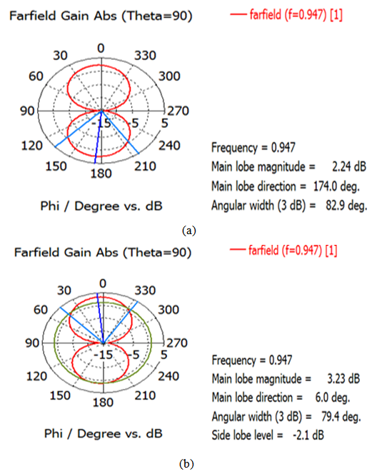 | Figure 10. E plane gain radiation patterns of the proposed antenna (a) without superstrate (b) with superstrate |
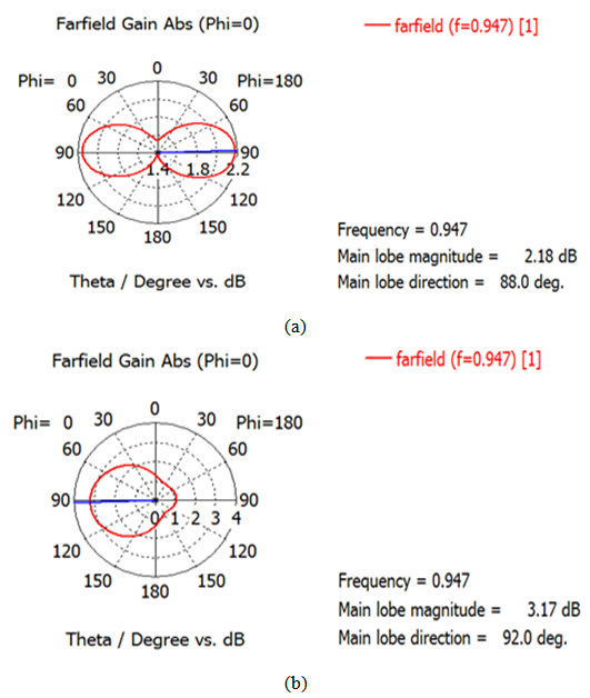 | Figure 11. H plane gain radiation patterns of the proposed antenna (a) with superstrate (b) with superstrate |
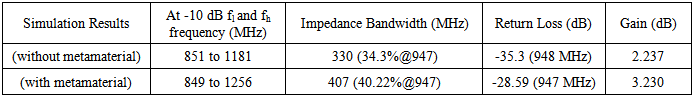 | Table 3. Summary on performance |
6. Conclusions
- Investigations on effect of a 5 x 5 DSRR superstrate introduced onto C -shaped patch antenna are discussed. The result showed that the impedance bandwidth and gain are enhanced to 23.33%, and 44.4% respectively; and a slight increase in return loss over the conventional patch antenna. Observation made showing that the proposed antenna is more directional, which is an important feature for RF energy harvesting antenna. The RF energy harvested using this antenna can be converted into DC voltage and power the low power devices such as mobile phones, sensors, webcams, etc. within the range of GSM-900 band. This will inherently prolong the life of the battery life of the mobile devices. As for the future enhancement on the performance of proposed antenna, the gain and the impedance matching can be further improved by using different structure of metamaterials.
ACKNOWLEDGEMENTS
- The work is funded by the Ministry of Education, Malaysia under the Fundamental Research Grant Scheme (FRGS); Grant No.: FRGS/2/2013/ ST02INTI/ 02/01.