Yusuf N. Y.1, Masdar M. S.2, Nordin D.1, Husaini T.3
1Department of Chemical and Process Engineering, Faculty of Engineering and Built Environment, Universiti Kebangsaan Malaysia
2Research Centre for Sustainable Process Technology (CESPRO), Faculty of Engineering & Built Environment, Universiti Kebangsaan Malaysia
3Fuel Cell Institute, Universiti Kebangsaan Malaysia
Correspondence to: Masdar M. S., Research Centre for Sustainable Process Technology (CESPRO), Faculty of Engineering & Built Environment, Universiti Kebangsaan Malaysia.
| Email: |  |
Copyright © 2015 Scientific & Academic Publishing. All Rights Reserved.
Abstract
In this new era, we faced several problems regarding global climate change that related with the CO2 emission that are harmful to living things and environment. Due to the concern of these global changes, fuel cell applications were knowledge by the industrial company to reduce the problem and being solutions for electrical power supply and transportations in the future. The fuel cell technology using hydrogen fuel specifically for polymer electrolyte membrane fuel cell (PEMFC) to create a chemical reaction that was used as electrical power. Hydrogen can be produced from diverse domestic feedstock’s using a variety of process technologies including biological processes. However, several issues need to be considered for the application of PEMFC using biohydrogen technologies such as purification system and the effect of impurities in H2 fuel. In this paper, the overviews of several issues in biohydrogen technologies are highlighted for fuel cell application. The hydrogen production including from biological pathway, the effect of impurities and gas purification technologies will be discussed based on the requirement of PEMFC.
Keywords:
Hydrogen, Fuel Cell, Membrane, Separation Technique
Cite this paper: Yusuf N. Y., Masdar M. S., Nordin D., Husaini T., Challenges in Biohydrogen Technologies for Fuel Cell Application, American Journal of Chemistry, Vol. 5 No. 3A, 2015, pp. 40-47. doi: 10.5923/c.chemistry.201501.06.
1. Introduction
The quest for understanding the natural world around us is as old as human consciousness. This quest continues in the present day, as scientists and researchers to investigate with increased intensity in the mysteries of physics, chemistry, and biology to unlock the secrets inherent in the physical universe in the world. One of the secret that being unlock is related to fuel cell technology in which the materials used to produce the fuel cell is based on natural element in earth such as biomass (a renewable resource made from renewable materials). Based on the advantages in terms of energy efficiency and ease of application, gasification is the best choice for exploiting energy from biomass [1]. Gasification can converts biomass into fuel gas (producer gas), consisting of hydrogen, carbon monoxide, carbon dioxide and nitrogen as major components along with some methane and other minor components. Through the concerns over global climate change are driving nations to reduce CO2 emissions, bio hydrogen is considered the fuel cell of choice for the electric power and transportations industries. Biohydrogen and biomethane will play important roles for future energy economy as clean, CO2 neutral and environmental friendly energy. The potential of bio-methane and bio-hydrogen production is not only decided by the characteristics and costs of the production process, but also by their integration into the overall energy infrastructure [2]. This would favour bio hydrogen production, especially when hydrogen is the preferred energy carrier for electricity generation in low temperature Proton Exchange Membrane (PEM) fuel cells. Bio hydrogen can be used directly in these cells, while methane requires reforming which will reduce the amount of generated electricity. Word green bio-methane on the other hand has the advantage that it can be applied in the existing natural gas infrastructure, while a substantial market demand for hydrogen will only arise in 20 years or more.Fuel cells are intrinsically much more energy efficient, and could achieve as high as 40–50% efficiency for transportation using proton exchange membrane fuel cells (PEMFC) or solid oxide fuel cells (versus the current efficiency of 20–35% with internal combustion (IC) engines [3]. The strategies and options of fuel processors depend on the type of fuel cells and the applications of it. Among the low temperature fuel cells, proton exchange membrane fuel cells require H2 as the fuel and thus nearly CO free and sulphur free gas feed must be produced from fuel processor. Thus, the proton exchange membrane fuel cell (PEMFC) being use to illustrate the science and technology behind the fuel cell concept, the characteristics and also the applications of the fuel cell technologies based on bio hydrogen production. As we know many synthetic reactions give mixture of products and it is necessary for us to separate the mixture of compound first to give the best performance in fuel cell technology. So, this separation can be achieved by differences in physical properties, such as boiling point, or by chemicals means, where the differences in physical properties are enhanced by chemical reactions. Based on above view, the separation method is important parts that need to be study through for future application in biohydrogen technology for fuel cell. Thus, the development of cost effective regarding separation technologies are being considerable interest for applications in advanced fossil based power and fuel technologies. Lastly, this biohydrogen technology has becomes one of the important parts to be studying for purification of hydrogen within the fuel cell applications and for the future technologies. Although, it is likely that fuel cells are classified according to the nature of the electrolyte and its performance, however, it is also requires particular materials and fuels to make it suitable for different applications use.
2. Hydrogen Production
Hydrogen with symbol of H2, is not an energy source, but is an energy vector or carrier due to its specialty on combinations with other chemical elements, which is why it always found as part of another substance, such as water, hydrocarbon, or alcohol. It is also been found in natural biomass, which includes plants and animals. That means that hydrogen has to be produced from one of the primary energy sources such as fossil fuels, nuclear, solar, wind, biomass, hydro, geothermal and urban waste resources. In the future, hydrogen is expected to become a significant fuel that will largely contribute to the quality of atmospheric air.Many researchers have been involved in analyzing the different hydrogen production methods based on energy and exergy analysis [4].There are several methods for producing or extracting hydrogen. A variety of process technologies can be used, including chemical, biological, electrolytic, photolytic and thermo chemical [5]. Each technology is in a different stage of development, and each offers unique opportunities, benefits and challenges. We can separate hydrogen atoms from water, biomass, or natural gas molecules. There are two most common methods for producing the hydrogen which are steam reforming and electrolysis (water splitting).
2.1. Method Producing Hydrogen
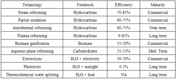
The production of hydrogen can be achieved via various process technologies, including thermal (natural gas reforming, renewable liquid and bio oil processing, biomass, and coal gasification), electrolytic (water splitting using a variety of energy resources), and photolytic (splitting of water using sunlight through biological and electrochemical materials). Table 1 shows some of the hydrogen production technologies summary. Hydrogen global production has so far been dominated by fossil fuels, with the most significant contemporary technologies being the steam reforming of hydrocarbons. Steam-methane reforming is currently the least expensive method of producing hydrogen and accounts for about 95% of the hydrogen produced in the United States. Steam reforming is a well-established technology that allows hydrogen production from hydrocarbons and water [6]. It is also used in industries to separate hydrogen atoms from carbon atoms in methane (CH4). Table 1. Hydrogen Production Technologies
 |
| |
|
However, the natural gas reforming process produces a product gasses mixture with significant concentrations of carbon monoxide, often 5 volume % or more (ca. 10 vol%). Thus, to increase the amount of hydrogen, the product gas is passed through a water-gas shift (WGS) reactor to decrease the carbon monoxide content, while at the same time increasing the hydrogen content. Typically, a high temperature is desired in order to get the fast kinetics production. Therefore, the reduction in the CO content of syngas is achieved in a two-step process that involves a high and a low temperature water-gas shift reaction, known as HTS and LTS processes, respectively in Figure 1. In the first step, carried out in the 310-450°C range with the use of Fe3O4/Cr2O3 as catalyst, the CO concentration is reduced from 10 to 3 volume %. In the second step, carried out in the 180-250°C range, the CO content is further reduced to the low level of 500 ppm using Cu, ZnO and Al2O3 as catalysts [7].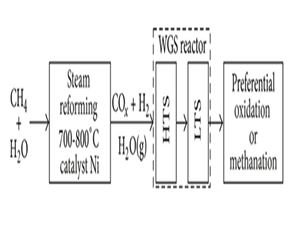 | Figure 1. A diagram of methane steam reforming with subsequent carbon monoxide conversion into carbon dioxide and hydrogen |
Another conventional technique is electrolysis, which applies electrical current to decompose water into hydrogen and oxygen molecules. In easy word, the electrolysis is a process that splits hydrogen from water. It results in no emissions but it is currently a very expensive process which requires a high energy. New technologies are being developed all the time. The electricity for electrolysis can come from any of the three energy sources. Hydrogen can also be produced via other means, including from algae by direct solar electrochemical processes, and from various nuclear-power-assisted pathways [7]. However, significant additional progress in some of these areas has been made in recent years, and some of them appear to be promising opportunities for producing hydrogen from renewable sources with less energy loss and potentially lower costs and fewer GHG emissions than is currently typical of industry practice.
2.2. Cost Manufacturing of Hydrogen
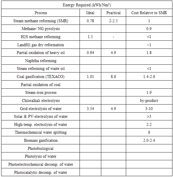
There are some important issues that we have to care about and one of them is related to the cost of manufacturing of hydrogen. Table 2 shows a listing of the cost and performance characteristics of various hydrogen production processes is as follows.Table 2. Cost and Performance Characteristics of Various Hydrogen Production, this table was originally published in IEEE Power & Energy
 |
| |
|
Based on Table 2, we could conclude that hydrogen produced by steam reformation costs approximately three times the cost of natural gas per unit of energy produced. This means that if natural gas costs $6/million BTU, then hydrogen will be $18/million BTU. Also, producing hydrogen from electrolysis with electricity at 5 cents/kWh will cost $28/million BTU which is slightly less than two times the cost of hydrogen from natural gas. Note that the cost of hydrogen production from electricity is a linear function of electricity costs, so electricity at 10 cents/kWh means that hydrogen will cost $56/million BTU. It has widely been accepted in bio-hydrogen research that the efficiency, performance and cost are the key factors affecting the hydrogen production.
2.3. BioHydrogen and BioMethane
At large scale systems bio hydrogen and bio methane is used for combined heat and power production. Nowadays, due to the commercialization of low cost and CO2 neutral hydrogen fuel cells that convert chemical energy of hydrogen directly to electricity with 50-60% electric efficiency, development of bio hydrogen and bio methane combined production from biodegradable residues becomes one of the important scientific and technological points. Thus, its required properties are high ionic conductivity which has zero electronic conductivity under cell operating conditions, long term chemical and mechanical stability at elevated temperatures in oxidizing and reducing environments, good mechanical strength with resistance to swelling, low oxidant and fuel crossover, pinhole free structure, interfacial compatibility with catalyst layers and low cost. However, there are major challenges that hinder the commercialization of bio hydrogen production processes including lower hydrogen yields and rates of hydrogen production. Thus, hydrogen is not commercialized as an energy source but it is widely used as a chemical reactant in the production of fertilizers, for refining diesel and for the industrial synthesis of ammonia.Biohydrogen can produce following a number of processes including direct bio photolysis, indirect bio photolysis, photo fermentation and dark fermentation. Among the hydrogen production methods, the most promising and environmentally friendly method seems to be dark fermentation from organic wastes as it combines the hydrogen generation with waste treatment [8]. Biomethane however is produced through anaerobic digestion. Methane production through anaerobic digestion of wastewater and residues (sewage sludge, manure and the organic fraction of municipal waste) is already broadly applied. Nevertheless, methane and hydrogen are in some aspects very similar. The ease and efficiency with which they can be converted to heat or electricity is comparable and both are relatively clean fuels (although hydrogen much more so than methane or natural gas). Fuel cells, one of the most important emerging technologies, can operate both on methane and on hydrogen. The main difference is that methane in the form of natural gas is a primary energy carrier whereas hydrogen is an intermediate produced from primary sources. Secondly, for natural gas a considerable infrastructure is in place today. The final product of anaerobic digestion is biogas which mainly consists of methane (55-75 vol%) and CO2 (25-45 vol%) [9]. Much of the interest in the biohydrogen economy concept is focused on the use of fuel cells to power electric cars and there is evident that fuel cells will play an important role for the use of both biomethane and biohydrogen because of their highly efficient energy conversion and near zero emissions. A fuel cell converts the chemical energy in hydrogen and oxygen into direct current electrical energy by electrochemical reactions. Fuel cells are devices that convert hydrogen gas directly into low voltage, direct current electricity. The key element in a fuel cell is the ion (proton) exchange membrane (PEM). The membrane is used to separate the electrode in the fuel cell. Its purpose is to separate the anode and cathode to prevent mixing of the fuel and oxidant and to provide an ionically conductive pathway for protons. During the process, mixed gas would produce on which mainly contains hydrogen and carbon dioxide, but may also contain methane, carbon monoxide, and hydrogen sulfide depending on different system and feedstock.
3. Fuel Cell
Fuel cells come in a variety of sizes, which the efficiency of production is independent of size. Individual fuel cells produce relatively small electrical potentials, about 0.7 volts, so cells are a stacked, or placed in series, to increase the voltage and meet an applications requirements. This means that individual fuel cells can be compiled on one another to form stacks, in turn; these stacks can be combined into larger systems. According to the U.S. Department of Energy, fuel cells are generally between 40-60% energy efficient [10]. This is higher than some other systems for energy generation. Thus, the fuel cell electric drive trains can provide a significant reduction in energy consumption and regulated emissions. The benefits of bio hydrogen and fuel cells are wide ranging, but will not be fully apparent until they are in widespread use by the world. Fuel cells can power virtually anything that runs on electricity. Although a few products are ready for the market today, many more are on the verge of commercial production. With the use of bio hydrogen in fuel cell systems, there makes very low to zero carbon emissions and no emissions of harmful ambient air substances like nitrogen dioxide, sulphur dioxide or carbon monoxide. Because of their low noise and high power quality, fuel cell systems are ideal for use in hospitals or IT centers, or for mobile applications. Early products introduced to the market will include portable fuel cells to replace batteries in computers, wheel chairs and cell phones. A few larger stationary fuel cells are already available today, and they show tremendous potential for providing cost effective distributed power, even in urban environments. Then, in future, vehicles will run on clean fuel cells, as reflected in recent announcements by the President of the United States and major carmakers.
3.1. Types of Fuel Cell
Since the invention of the "gas battery" by Robert Grove in 1839, several different fuel cell types have been developed. Each type has operating characteristics and temperatures that are suitable for certain applications but not for others. Fuel cell technologies are named for their electrolyte since the electrolyte defines the key properties, particularly operating temperature, of the fuel cell. Those type being classified by the electrolyte used, each has various ad-vantages and disadvantages relating to cost, temperature, fuel purity, size, and lifetime. However, even there are several fuel cell types with features applicable to certain fields, PEMFCs are the most promising system in terms of providing a continuous electrical energy supple from fuel with high levels of energy efficiency, power density and compactness. Therefore, in recent years, many studies on PEMFC technology and its application have been worldwide due to the membrane technologies as advance separation technology nowadays.A schematic cross section of a single cell of a PEMFC showing individual components is shown in Figure 2. An individual cell consists of membrane. Each electrode has an electro catalyst layer, and a gas diffusion layer (GDL). The catalyst layers can be attached to either the membrane or at times to the GDL material (termed the gas diffusion electrode, GDE). Finally, the PEM is typically a polymeric material with sulfonic-acid side chains and a fluorocarbon or hydrocarbon backbone. Nafion (Nafion is a trademark of E. I. DuPont de Nemours and Company), a perfluorinated sulfonic acid based ionomer (PFSA), has been the standard membrane material for fuel cell applications and is also the most studied fuel cell membrane material.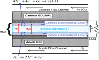 | Figure 2. Schematic cross section of a typical PEM fuel cell |
3.2. PEMFC Application
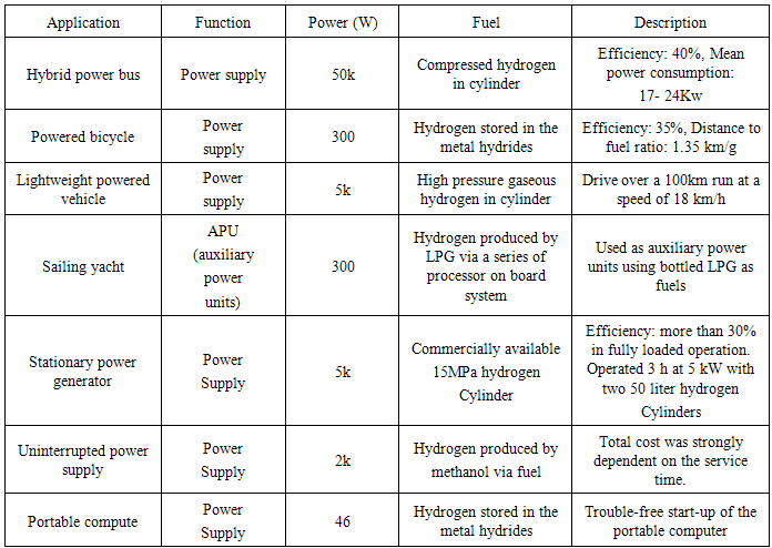
Generally, there are three main application fields for a PEMFC system such as transportation, stationary and portable applications [11]. The development direction of PEMFCs in each nation is bound up with their social and industrial environment as well as their structure of energy supply and demand for future. Table 3 shows the PEMFC in each application as well as the results of the application tests carried out in the world since 2002.Table 3. Various application test of PEMFC on-board reported since 2002, Originated Publish by J.-H. Wee / Renewable and Sustainable Energy Reviews 11 (2007) 1720 1738
 |
| |
|
The potential for the PEMFC lies in its use for transport application. For the stationary applications cost reduction becomes possible if this type of fuel cell finds broad use for transport applications and is expected to make the technology competitive. According to that reason, one could easily see the potential of this promising alternative technology through the development of environment friendly vehicles, with near zero emission and highly efficient energy conversion due to the bio hydrogen used. Therefore, the success of PEMFC in this field is an important factor for expanding their applications to the fields. In order to meet the future technology especially on vehicle or transportation needs, most major inventor in the world actively engaged in developing prototypes Fuel Cell Vehicles (FCVs) and assessing their performance. The development of a FCV requires the on-board integration of a fuel cell system and electric energy storage devices, with an appropriate energy management system [12]. Finally, considering the social and health benefits on using PEMFC, it is desired that there should be more focus on developing hydrogen production technology such as electrolyzing water using excess electricity from wind turbines or solar cells. However, PEMFC most likely will use reformed fuel as the primary source for the anode feed which always contains carbon dioxide, nitrogen, carbon monoxide, and trace amount of hydrogen sulfide [13]. This could effects the PEMFC and make it becomes less effective in terms of performance due to its high in impurities, contaminated with the mixture of gases.
3.3. Effects of Impurities in PEMFC
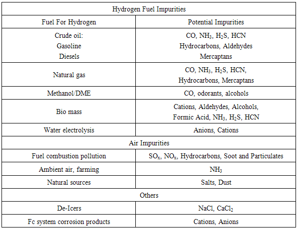
Impurities present in both the bio hydrogen fuel stream and the air intake have been shown to negatively impact a fuel cell’s performance and durability. The most important component in the PEMFC is the MEA which assembly of anode, proton conducting membrane and cathode. MEA or mean absolute error is used to measure how close predictions to the actual data values (higher performance). Table 4 lists the most common impurities and their sources. Impurities are known to affect FC performance by various mechanisms that lead to performance loss. Impurities that adsorb onto the anode or cathode electro catalyst surface inhibit the electrode charge transfer processes, resulting in interfacial over potential losses. The impurities such as ammonia, which can form cations, or other cations introduced to the cell directly from salts or corrosion byproducts can cause ion exchange with protons in the ionomer. These cations lower proton conduction and can result in increased ohmic losses. Table 4. Origin of Common Fuel and Air Impurities
 |
| |
|
PEMFCs are considered to be promising candidates over other types of fuel cells for future electric power generation devices used in portable, transportation, and stationary applications. However, material cost, fuel availability and storage, durability, and tolerance to impurities are major barriers to fuel cell implementation. Typically, a PEMFC utilizes air as an oxidant and hydrogen fuel generated by an external reforming of hydrocarbons with steam, air, or a combination of these two. Reforming yields a bio hydrogen rich steam containing small amounts of impurities such as CO, NH3, CO2, hydrocarbons, sulfur compounds and other gas. However, even the best contaminant clean up systems such as preferential oxidation (PROX), selective methanation, H2 selective membrane, pressure or temperature swing adsorption (PSA, TSA) and others, could also leave residual amounts of impurities, and which can severely affect the performance of fuel cell.It is known that in the absence of impurities, the process for H2 activation at the anode in a PEMFC is relatively fast compared to that for proton transport via the catalyst layers and the membrane to the cathode. In the presence of contaminants, on the other hand, PEMFC performance could be limited by the kinetics of hydrogen oxidation reaction (HOR) and oxygen reduction reaction (ORR) on catalysts and/or proton transport within the catalyst layers and the membrane, depending on operating conditions, types and concentrations of impurities, and tolerance of impurities to fuel cell components [14]. For example, previous studies have found that even trace amounts (10-50 ppm) of CO significantly deteriorate the efficiency of the fuel cell due to the decrease in hydrogen surface concentration and the slow rate of hydrogen dissociation on catalysts.Even if a fuel cell is operated in neat H2 fuel and oxidant streams, it has been confirmed that the degradation of PEMFC performance can occur due to formation of H2O2 and material corrosion during fuel cell operations. It significantly affects the hydrogen oxidation reaction (HOR) on Pt in the anode catalyst layer by interacting strongly to the Pt surface and blocking sites for H2 dissociation [15]. Electrode performance decreased by impurities and the effects makes fuel cell efficiency decreases, higher Pt loading required to maintain performance in presence of impurities increases cost and durability may decrease in the presence of those impurities. The effect of CO2 and a few example hydrocarbons has been studied on Pt/C and PtRu/C anodes using stripping cyclic voltammetry, in inert gas and in the presence of bio hydrogen, and constant load experiments, where the fuel cell has been run with oxygen on the cathode and pure or contaminated of bio hydrogen on the anode. Electrochemical impedance spectroscopy and mass spectrometry have also been used to monitor the build-up of resistance in the cell with time during exposure to impurities and to analyses the products in the outlet stream of the anode, respectively. The effect of adsorption potential, cell temperature, humidity of the feed gases and concentrations of selected impurities has been studied by some researcher nowadays. Therefore, purification system is one of the important things and be needed to purify the mixture of gas especially hydrogen, H2, up to 99.99% effectiveness.
4. Gas Separation and Purification
For the best understanding of the technology nowadays, we need to learn more about the operating system of gas separation and membranes technology. There are the explanations of some of the separation method to obtain the optimum understanding of the process occurring on the system deeply on purify the gasses mixture. These separation methods, being used nowadays for the purifying the mix gas and eliminate the impurities for better applications in future. There are 3 basic concepts for separating the mixture gasses which are separation with sorbents or solvents, membrane separation and cryogenics separation. First, for separations of solvents, such as amine scrubbing technology, was established over 60 years ago in the oil and chemical industries, for removal of hydrogen sulphide and CO2 from gas streams Commercially, it is the most well-established of the techniques available for CO2 capture although practical experience is mainly in gas streams which are chemically reducing, the opposite of the oxidising environment of a flue gas stream. Mono ethanolamine (MEA) is a widely used type of amine for CO2 capture. CO2 recovery rates of 98% and product purity in excess of 99% can be achieved. There are, however, questions about its rate of degradation in the oxidising environment of a flue gas and the amount of energy required for regeneration as in Figure 3.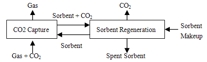 | Figure 3. Separation with Solvents and Sorbents |
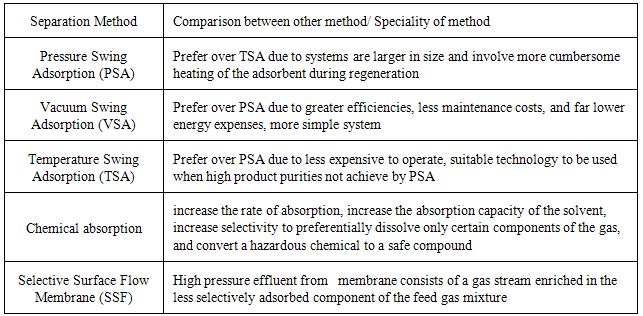
For a sorbent part like solid adsorbents, such as zeolites and activated carbon, this can be used to separate CO2 from gas mixtures. For an example, in pressure swing adsorption (PSA), the gas mixture flows through a packed bed of adsorbent at elevated pressure until the concentration of the desired gas approaches equilibrium. The bed is regenerated by reducing the pressure. In temperature swing adsorption (TSA), the adsorbent is regenerated by raising its temperature. PSA and TSA are commercially practiced methods of gas separation and are used to some extent in hydrogen production and in removal of CO2 from natural gas. Adsorption is not yet considered attractive for large-scale separation of CO2 from flue gas because the capacity and CO2 selectivity of available adsorbents is low. However, it may be successful in combination with another capture technology. Table 5 shows a comparison of few types of separation method.Table 5. Comparison of Separation Method
 |
| |
|
Secondly are gas separation membranes, as Figure 4, which allow one component in a gas stream to pass through faster than the others. There are many different types of gas separation membrane, including porous inorganic membranes, palladium membranes, polymeric membranes and zeolites. Membranes cannot usually achieve high degrees of separation, so multiple stages and/or recycle of one of the streams is necessary. This leads to increased complexity, energy consumption and costs. Several membranes with different characteristics may be required to separate high purity of CO2. Solvent assisted membranes are being developed to combine the best features of membranes and solvent scrubbing. Much development is required before membranes could be used on a large scale for capture in power stations. Membrane separation has the advantages of steady state operation, absence of moving parts and modular construction and hence has been applied successfully for the separation of CO2 from light hydrocarbons in the petroleum and natural gas industries [16]. 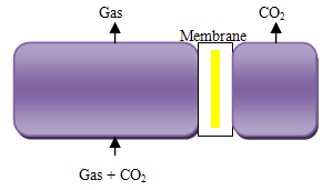 | Figure 4. Separation with membrane |
Last method is cryogenic; those CO2 gas can be separated from other gases by cooling and condensation. Cryogenic separation is widely used commercially for streams that already have high CO2 concentrations (typically >90%) but it is not used for more dilute CO2 streams. A major disadvantage of cryogenic separation of CO2 is the amount of energy required to provide the refrigeration necessary for the process, particularly for dilute gas streams. Another disadvantage is that some components, such as water, have to be removed before the gas stream is cooled, to avoid blockages. Cryogenic separation has the advantage that it enables direct production of liquid CO2, which is needed for certain transport options, such as transport by ship. Cryogenics would normally only be applied to high concentration, high pressure gases, such as in pre-combustion capture processes or oxygen fired combustion as Figure 5.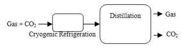 | Figure 5. Separation by cryogenic distillation |
There are some other method purifications being discussed here which are vacuum swing adsorption (VSA). Vacuum swing adsorption (VSA), it is a non-cryogenic gas separation technology. Using special solids, or adsorbents, VSA segregates certain gases from a gaseous mixture under minimal pressure according to the species' molecular characteristics and affinity for the adsorbents. These adsorbents (such as zeolites) form a molecular sieve and preferentially adsorb the target gas species at near ambient pressure. The process then swings to a vacuum to regenerate the adsorbent material. For the membrane separation technology, the widely used in membrane separation processes are include microfiltration, ultrafiltration, nanofiltration, reverse osmosis, electrolysis, dialysis, electrodialysis, gas separation, vapor permeation, pervaporation, membrane distillation, and membrane contactors. Microfltration and ultrafiltration is widely used in food and beverage processing (beer microfiltration, apple juice ultrafiltration), biotechnological applications and pharmaceutical industry (antibiotic production, protein purification), water purification and wastewater treatment, microelectronics industry, and others. Nanofiltration and reverse osmosis membranes are mainly used for water purification purposes. However, among all the process above, reverse osmosis and ultafiltration are the most widely used in industry. Based on reason above, we conclude that membrane separation as one of the advance separation technology for future applications based on bio hydrogen.
5. Conclusions
In addition to the more conventional methods of SMR, gasification, and grid-powered electrolysis, a new suite of renewable production options such as from biological pathway are emerging for hydrogen production. The fuel cell technologies are considered to be promising candidates, such as PEMFC using hydrogen fuel, for future electric power generation devices used in portable, transportation, and stationary applications. The present of impurities in bio-hydrogen fuel have been shown to negatively impact a fuel cell’s performance and durability. Therefore, purification system is one of the important things and needed to purify the mixture of gases in bio-hydrogen production up to 99.99% of hydrogen purity.
ACKNOWLEDGEMENTS
This study was partially supported by UKM – YSD Research Project under code KK-2014-013.
References
| [1] | Deshmukh, R, Jacobsan, A, Chamberlin, C, Kammen, D. Thermal gasification or direct combustion? Comparison of advanced cogeneration systems in the sugarcane industry Biomass Bioenergy, 2013. |
| [2] | Reith J.H., R.H. Wijffels and Barten, H., Bio-methane & Bio-hydrogen, Status and perspectives of biological methane and hydrogen production, Dutch Biological Hydrogen Foundation on behalf of the contributing authors, 2003. |
| [3] | C. Song, Fuel processing for low-temperature and high temperature fuel cells: challenges, and opportunities for sustainable development in the 21st century, Catalysis Today, vol. 77, Issues. 1-2, pp. 17–49, December 2002. |
| [4] | Kevin R. Fall, W. Richard Stevens, TCP/IP Illustrated, Volume 1: The Protocols, 2nd ed., Addison-Wesley, USA, 2011. |
| [5] | Oecd/Iea, Hydrogen Production and Storage, International Energy Agency (IEA), Head of Publications Service, France, 2005. |
| [6] | University of Central Florida. The Florida Solar Energy Center (FSEC) is a research institute of the University of Central Florida, 2007 – 2014. |
| [7] | Guo, X.M., Trably, E., Latrille, E., Carrere, H., Steyer, J.P., Hydrogen production from agricultural waste by dark fermentation: A review. Int. J. Hydrogen Energy. 35, 10660-10673. 2010. |
| [8] | Lipman, T.E. What Will Power the Hydrogen Economy? Present and Future Sources of Hydrogen Energy, Institute of Transportation Studies, University of California - Davis, UCD-ITS-RR-04-10, July, 2004. |
| [9] | Benemann, J., Hydrogen biotechnology: Progress and prospects. Nature Biotechnology 14(9):1101-1103. 1996. |
| [10] | Nice, Karim and Strickland, Jonathan. How Fuel Cells Work: Polymer Exchange Membrane Fuel Cells. How Stuff Works, 2011. |
| [11] | Types of Fuel Cells. Department of Energy EERE website, 2011. |
| [12] | Wee J.H., Applications of proton exchange membrane fuel cell systems Department of Chemical and Biological Engineering, Korea University, Received 16 January 2006; accepted 19 January 2006. |
| [13] | McNicol B.D, Rand D.A.J, Williams K.R. Fuel cells for road transportation purposes yes or no? J Power Sources 2001. |
| [14] | Fuel cell handbook, 5th ed. West Virginia: US Department of Energy; 2000. |
| [15] | Hongsirikarn, K., Effect of Impurities on Performance of Proton Exchange Membrane Fuel Cell Components, 2010. |
| [16] | Kothandaraman, A., Carbon Dioxide Capture by Chemical Absorption: A Solvent Comparison Study, © 2010 Massachusetts Institute of Technology, June 2010. |
 Abstract
 Reference
 Full-Text PDF
 Full-text HTML