Wai Ling Kong1, Mohd Shahbudin Masdar2, Azran Mohd Zainoodin2
1Department of Chemical and Process Engineering, Universiti Kebangsaan Malaysia, UKM Bangi, Selangor, Malaysia
2Fuel Cell Institute, Universiti Kebangsaan Malaysia, UKM Bangi, Selangor, Malaysia
Correspondence to: Mohd Shahbudin Masdar, Fuel Cell Institute, Universiti Kebangsaan Malaysia, UKM Bangi, Selangor, Malaysia.
| Email: |  |
Copyright © 2015 Scientific & Academic Publishing. All Rights Reserved.
Abstract
Direct liquid fuel cell is a type of innovative energy source where the generation of power thru the utilization of liquid fuel such as methanol, formic acid and ethanol. Two types of liquid fuel were tested using a commercial 20W polymer electrolyte membrane fuel cell (PEMFC), Horizon H-20, by manipulating the molarity of the liquid fuel in semi passive mode. The optimum concentration for direct methanol fuel cell (DMFC) was at 5M where the voltage output approaches 1.06V and 229.5 mW whereas the optimum concentration of direct formic acid fuel cell (DFAFC) was at 8M where the output voltage reaches 3.5V and 56.06 mW. The potential of formic acid as liquid fuel which provides stable performances, i.e., voltage, current and power, is observed where the crossover rate and mass transport limitations are overcome. A passive DFAFC was fabricated with Pt black as catalyst on cathode and Pd at anode. The DFAFC was tested with formic acid at various concentrations and found that the best performance was at 530 mW using 10M formic acid. A long term performance test of the passive DFAFC stack was carried out to study its stability in performance.
Keywords:
Fuel cell, Semi-Passive DMFC, Passive DFAFC, DLFC, Formic acid
Cite this paper: Wai Ling Kong, Mohd Shahbudin Masdar, Azran Mohd Zainoodin, Performances on Direct Liquid Fuel Cell in Semi-Passive and Passive Modes, American Journal of Chemistry, Vol. 5 No. 3A, 2015, pp. 35-39. doi: 10.5923/c.chemistry.201501.05.
1. Introduction
Direct Liquid Fuel Cell (DLFC) is the device that generates energy through electrochemical reactions where the power and heat energy are generated through liquid fuel cell that is rich in hydrogen content. Unlike the conventional energy carrier like battery, combustion of fuel is not required. Hence, zero-emission of greenhouse gasses is attained where it can be concluded as an innovative green power source [1]. Recently, increasing attention has been swift from direct methanol fuel cell (DMFC) to direct formic acid fuel cell (DFAFC), where the major different between these two categories are the characteristic of the liquid fuel- methanol and formic acid. The hindering issues in DMFC commercialization technology arise from DMFC such as low methanol electro-oxidation rate and high methanol crossover rate. Hence, formic acid emerges as a potential alternative fuel where it has relatively high electro-catalytic oxidation rate and low crossover rate [2]. Besides methanol and formic acid, other alternatives fuel can be utilized including phosphoric acid and potassium hydroxide where appropriate catalyst is needed to be clarified for its optimum performances [3]. In previous years, massive studies are carried out on the single-cell DLFC on its performances under various parameters, a stable and portable energy carrier is in niche for the future DLFC technology. Hence, in this study, the performances on semi-passive DLFC was studied while another passive DFAFC stack was fabricated and its performance was investigated. The DFAFC stack was fabricated at the specification where its configuration was fully portable and no auxiliary equipment was required prior to its operation.
2. Experimental
The study was clearly divided into two categories where the first category was on the performances of DLFC from Horizon H-20 model in semi-passive mode, while the second category was on the performances of customize-fabricated with a fully passive DFAFC stack.The liquid fuel used in the Horizon H-20 were methanol and formic acid where in the second category, only formic acid was used as the customized MEAs were built specifically to operate with it.
2.1. Performance of DLFC on Various Parameters at Semi Passive Mode
The PEMFC Horizon H-20 stack was used as a DLFC and was tested as a DMFC and DFAFC at semi-passive mode. The peristaltic pump was used to pump the fuel from 200 ml fuel reservoir and maintain the circulation of the liquid fuel, i.e., methanol and formic acid, into the fuel cell and the flow rate was fixed at 30 ml min-1. Methanol (DMFC) and formic acid (DFAFC) was tested in various concentrations from 1M to 10M to obtain the optimum operating condition of the DLFC. The electrochemical performance of the DLFC was measured using Potentiostat/Galvanostat (Wonatech WMPG 1000). To know the consumption of fuel during its operation, the concentration of fuel was measured before and after experiments using Density Meter (DMA35 Anton Paar).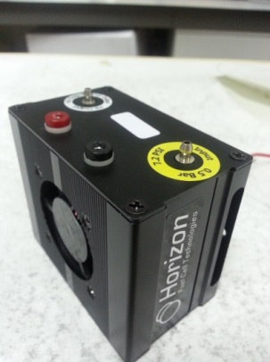 | Figure 1. PEMFC Horizon H-20 with DLFC operation |
2.2. Performance of Passive DFAFC Stack on Various Parameters
2.2.1. Fabrication of DFAFC Stack
General structures of DFAFC stack consist of the body stack, gasket, current collector, membrane electrode assembly (MEA) and the end plate cover. The DFAFC stack is designed in a rectangular shape with the fuel reservoir capacity of 800ml in the middle where the MEA compartments surrounded the fuel reservoir. The support material of the stack body was polycarbonate where the stack was designed to have eight cells. The current collector was made of 316L stainless steel plate with parallel flow field pattern with 1.2 mm in thickness. Connection port for wiring was built on top of the current collector to enable the connection of the circuit by using external wire, bolts, nuts and washer. The liquid fuel formic acid was pre-loaded into the reservoir for the DFAFC to operate passively. To prevent a solution leakage in the reservoir as well as within the cell, the silicone rubber gaskets were used to seal the layers between current collector, MEAs, end plate cover and the reservoir. Figure 2(a) and Figure 2(b) shows the DFAFC stack and the external wiring connection.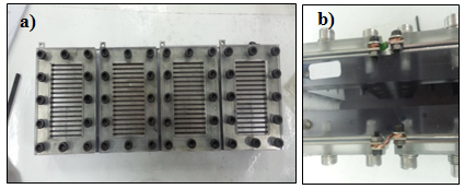 | Figure 2. Passive DFAFC developed (a) DFAFC stack (b) external wiring connection |
2.2.2. Fabrication of Membrane Electrode Assembly
Fabrication of MEAs including the process of diffusion layer (DL) casting and catalyst layer casting. In this study, the catalysts used were Platinum black and Palladium black for cathode and anode, respectively. A conventional method of painting technique was used. a. Diffusion Layer (DL)A commercial Toray carbon paper TGP-H-060 from Fuel Cell Store was used as the carbon backing layer and cut into dimension of 8.5cm x 4.5 cm to ensure the minimum active area to be 8cm x 4cm. For the preparation of the carbon black (DL), a minimum loading of 1 mg cm-2 and 50% loss is taking into assumption. In the DL casting material preparation, 0.128g of carbon black was homogenized with 2.56g of isopropyl alcohol (IPA) in ultrasonic until the mixture turns into paste-like. The mixture was then followed by the addition of 0.2816g of Nafion solution and homogenize as well in ultrasonic water bath.After the mixture of carbon black, IPA and Nafion is fully homogenized, the casting procedure was carried out layer by layer onto the Toray carbon paper at an active area of 8cm x 4 cm. All carbon papers with casted material are placed in oven of 100°C for 1 hour for drying process. Weight the dry mass of the casted carbon paper to obtain the actual loading of the DL layer to ensure minimum requirement achieved. b. Cathode Catalyst LoadingPlatinum black was used as the catalyst for cathode with 2 mg cm-2 catalyst loading. The casting material begins with 0.096g of platinum black and moisture with distilled water. 0.192g of IPA was added into the catalyst and homogenized in the ultrasonic water bath until paste-like catalyst ink was formed. 0.3392g of Nafion was added later on and homogenized as well. The catalyst ink was casted layer by layer onto the GDL-casted carbon papers and placed in the oven at 110°C for 1 hour for drying purpose. The cooled carbon paper was removed and weighed to obtain the actual loading of catalyst.c. Anode Catalyst LoadingPalladium black was used as the catalyst at the anode. Similar preparation procedure was used in the anode catalyst loading procedure as in the cathode catalyst loading where the platinum black is replaced by palladium black. d. MEA Hot PressingNafion 212 membrane was used in the MEA hot pressing and no pre-treatment is required. The membranewas cut into dimension of 5cm x 9cm. The cathode and anode casted carbon paper are placed in the centre of the Nafion 212 membrane with the catalyst side facing inwards.Nafion 212 sandwiched with the electrodes were wrapped in aluminium foil and hot pressed at temperature of 135°C and 20 bars for 3 minutes. It was then cooled down and fixed at the MEA compartment on the DFAFC stack with anode facing inwards. The MEAs are activated by supplying 800ml 1M formic acid into the liquid fuel reservoir for 24 hours under ambient temperature.
2.2.3. Operation of Passive DFAFC
Formic acid solutions were prepared at 2M, 4M, 6M, 8M and 10M, respectively. Starting with 800ml of 2M formic acid solution with the anode in contact with the solution and cathode in contact with the ambient air, each cell is connected in series using external wiring connection. The performance of the passive DFAFC stack is measured using Fuel Cell Monitor Pro 3.0. Transformer reading card is connected to the passive DFAFC as shown in Figure 3. Performance of the stack is measured in terms of maximum voltage, current and power as a whole stack and every single cell respectively. 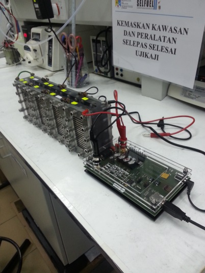 | Figure 3. Connection of passive DFAFC to the transformer card of Fuel Cell Monitor Pro 3.0 |
The stack performance was measured on 4M, 6M, 8M and 10M. In this study, 6 cells were used and connected in series where the performance of each cell is measured. The optimum concentration of the liquid fuel is identified and run for a long-term operation of 5 hours consecutively to test on its stability.
3. Results and Discussion
The results and discussions are further divided into two segments as well, which are the performance result on PEMFC Horizon H-20 with DLFC operation and customize-fabricated passive DFAFC.
3.1. Performance of DLFC with Horizon H-20 at Semi Passive Mode
For liquid fuel methanol, the performances of the DMFC are shown at Figure 4 while for DFAFC performances are shown in Figure 5. Figure 4 shows that the optimum voltage decreased while the maximum power increased with increasing the methanol concentrations from 1M to 5M. For instance, at 1M, the optimum voltage was obtained at 1.53V and the maximum power at 120 mW, while at 5M, the maximum power was recorded at 229.5mW and optimum voltage at 1.1V. It was easily understood that the increasing maximum power with concentrations due to the increasing of methanol transport for anode reaction. However, the decrease in optimum voltage with concentrations was affected by mixed potential due to methanol crossover which its increased with methanol with concentration. Methanol cross over is a severe matter where the direct diffusion of molecules from anode to cathode and directly oxidized by the air at the positive electrode can reduce the performance of DMFC. Hence, methanol must be first diluted in order to reduce methanol cross over, followed by a proportional increment of active surface area to compensate with the lower methanol concentration.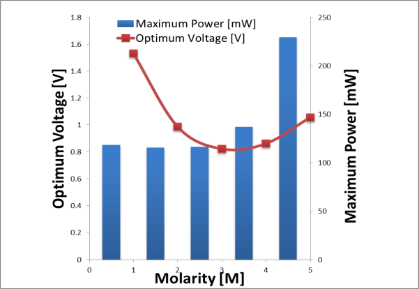 | Figure 4. Optimum voltage and maximum power of DMFC at various methanol concentrations |
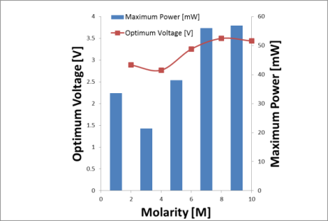 | Figure 5. Optimum voltage and maximum power of DFAFC at various formic acid concentrations |
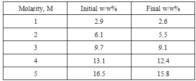
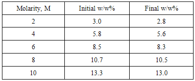
Meanwhile, from Figure 5, the optimum concentration of formic acid for DFAFC falls into the range of 8M-10M, where the optimum voltage recorded at 3.5V and 3.44V respectively. The maximum power of DFAFC of 8M and 10M were recorded at 56.06mW and 56.87mW as well. The inconsistent occurs here does not deviates much where we can conclude that, for better liquid fuel saving, 8M will be the best concentration for formic acid to perform best in DFAFC. As compared to DMFC where methanol is used as liquid fuel, formic acid required a relatively higher concentration in order to perform. This is due to the chemical reaction occurs where methanol released 6 protons and electrons throughout the electro-oxidation process. In contrast, formic acid only produces 2 protons and electrons from the electro-oxidation of formic acid. Therefore, under the same performance to be achieved, a relatively higher formic acid molecules need to be transferred through the catalyst layers. The utilization rate of methanol and formic acid throughout the operation is tabulated in Table 1 and Table 2 respectively. For DMFC, the methanol utilization rate ranged from 0.3 w/w% to 0.7w/w%. The utilization rate of formic acid in DFAFC ranged from 0.2 w/w% to 0.3 w/w%. For both cases DMFC and DFAFC operation, it was understood that the decreasing of fuel concentration due to fuel consumption for the anode reaction. In case of DMFC operation, the decreasing in fuel slightly higher compared to that formic acid might be contributed by two factors. One is the higher utilization rate in anode reaction, and hence increases the maximum power as shown in Figure 4. Furthermore, it was suggested that a methanol crossover occurred during the operation, and hence reduced the methanol concentration in the reservoir. Table 1. Utilization of methanol in DMFC
 |
| |
|
Table 2. Utilization of formic acid in DFAFC
 |
| |
|
3.2. Passive DFAFC
The performance of every each cell for 4M formic acid concentration is shown in Figure 6. The inconsistent performance of every single cell may cause by the inconsistent catalyst loading of the MEAs, which affect the electro-oxidation rate of formic acid.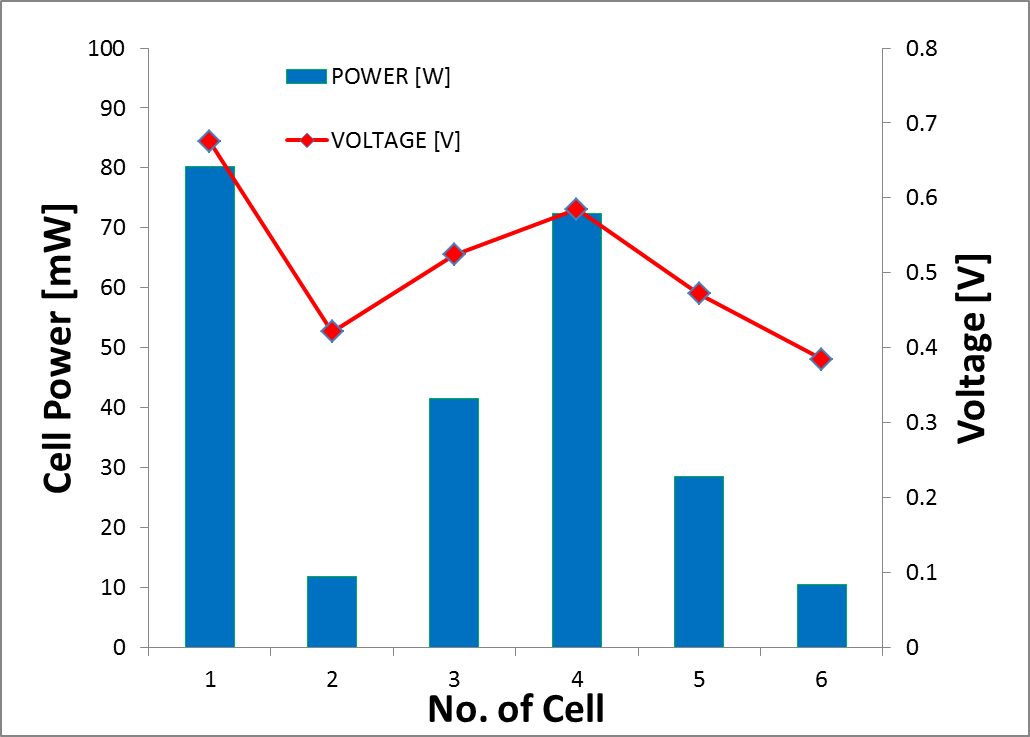 | Figure 6. Maximum power and voltage for each cell in passive DFAFC stack at 4 M formic acid concentration |
The performance of passive DFAFC as a whole stack connected in series at concentration of formic acid ranging from 2M to 10M is shown in Figure 7.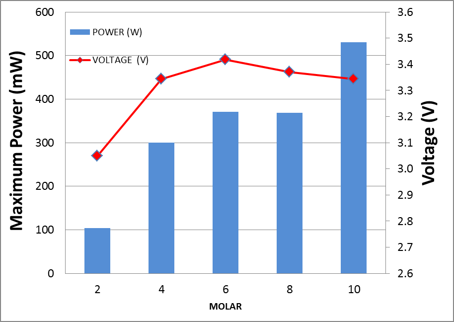 | Figure 7. Performance of DFAFC stack at different fuel concentration from 2M to 10M |
From the measurement, it was found that the optimum concentration of formic acid for the operation of passive DFAFC was at 10M where the maximum power was recorded at 530 mW. As compared to Horizon H-20 with DLFC operation, the optimum operation condition was at 8M, however the passive DFAFC required relatively higher concentration of formic acid. This can be explained by the transport rate of formic acid at anode’s catalyst. With a pump, it was expected that concentration rate of formic acid would be higher compared to that passive type. Therefore, higher formic acid concentrations were needed for passive type operation. A long term operation with 6M formic acid was carried out for 5 hours continuously. The stability of the performance is observed through the voltage of the passive DFAFC. Figure 8 shows the voltage generated by the passive DFAFC stack in 5 hours. It shows that the voltage for the first 90 minutes depreciates significantly from 3.37V to 2.87V or up to 29.7% depreciation (5.56 mV min-1). However, the performance of the passive DFAFC stack approaches its stability after 90 minutes. At the end of 5 hours, the voltage changes from 2.87V to 2.65V or up to 7.6% depreciation within 210 minutes (1.05mV min-1). 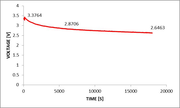 | Figure 8. Performances of passive DFAFC for 5 hours run in terms of voltage |
It was suggested that the decreasing performance was caused by the abrupt depletion of fuel and the accumulation of carbon monoxide at the anode interface which creates the diffusion resistance. At the initial stage, the difference in concentration of formic acid at the anode interface and the bulk solution will require time for the diffusion of formic acid to occur as well as the removal of carbon monoxide Thus, the passive DFAFC achieving stability after 90 minutes where the rate of diffusion of formic acid and carbon dioxide removal achieved a constant rate.
4. Conclusions
A commercial PEMFC Horizon H-20 was used in this study to obtain the optimum operating condition of both DMFC and DFAFC using semi passive operation. The investigation showed that the optimum operating condition of DMFC was at 5M methanol and 8M formic acid for DFAFC. The best performance of DMFC noted a maximum power of 229.5mW and 56.9 mW for DFAFC. For a customize-fabricated passive DFAFC stack, the best performance is recorded at formic acid concentration of 10M, which achieved maximum power of 530 mW. Meanwhile, the study on the stability of the performance of the passive DFAFC is investigated where it can conclude that the stack produce stable voltage output for long run.
ACKNOWLEDGEMENTS
Tis study was fully supported by Dana Universiti Penyelidikan DLP-2013-026 and GUP 2014-069 from University Kebangsaan Malaysia.
References
| [1] | Online Available: http://www.fuelcelltoday.com |
| [2] | Weiwei Cai, Liang Yan, Chenyang Li, Liang Liang, Wei Xing, “Development of a 30W Class Direct Formic Acid Fuel Cell Stack With High Stability and Durability” Elsevier Publishing, International Journal of Hydrogen Energy, vol.37, pp.3452-3432, 2012. |
| [3] | Holland, B., Zhu, J. & Jamet, L., “Fuel Cell Technology and Application”, University of Technology, Sydney, Australia, 2007. |
| [4] | Hacquard, A., “Imrpoving and Understanding Direct methanol Fuel Cell (DMFC) Performance”, Master of Science, Chemical Engineering Worcester Polytecnic Institute, Massachusetts, 2005. |
| [5] | S.K, Kamarudin, F. Achmad, W.R.W. Daud, “Overview on The Application of Direct methanol Fuel Cell DMFC) for Portable Electronic Devices”, Elsevier Publishing, International Journal of Hydrogen Energy, vol34, 99. 6902-6916, 2009. |
 Abstract
 Reference
 Full-Text PDF
 Full-text HTML